
Inline Pump Selection Guide for Water Supply and HVAC Systems
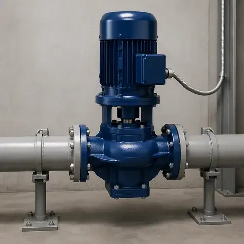
In this inline pump selection guide, the focus is on four numbers that drive every successful installation: flow, total dynamic head (TDH), available NPSH, and the physical clearance your maintenance team needs. Get those right, and you’re in a much stronger position to avoid the two most expensive mistakes we see in commercial buildings—cavitation damage that eats impellers far sooner than expected, and oversized pumps running so far from their best efficiency point that energy bills quietly climb year after year.
This guide walks through the full selection framework used when sizing inline centrifugal pumps for chilled water loops, condenser water systems, domestic water booster sets, and high-rise pressure zones. By the end, you’ll know when a vertical inline design actually reduces long-term maintenance cost versus when a horizontal inline layout is the safer choice, what VFD operating range gives stable control without minimum flow problems, and exactly what technical data every supplier needs before they can quote a pump that fits rather than one that barely works.
Think of this as your pre-RFQ sanity check. If you’re comparing supplier proposals right now, jump to the NPSH verification section and the RFQ checklist—those two pieces alone have stopped more bad selections in my career than any catalog comparison ever could.
Quick Answer: 30-Second Inline Pump Decision Logic
Start here. If you answer “no” to any of these, stop and resolve that gap before looking at pump curves.
- Flow and TDH are calculated from your system curve—not estimated from pipe size or past projects.
- NPSH available minus NPSH required should maintain an application-appropriate safety margin across the full operating range, not just at the design point. Many HVAC and water supply projects use roughly 0.5–1.5 m as a starting engineering guideline, but the acceptable margin depends on liquid temperature, duty stability, suction conditions, and the manufacturer’s published curves for the selected pump.
- The pump will operate within 70–120% of BEP flow for most of its running hours. If not, a VFD alone won’t fix the mismatch.
- You can confirm pipe loads on the pump flanges won’t exceed the manufacturer’s allowable limits—especially for vertical inlines where the motor sits on top.
- Horizontal or vertical layout is decided by maintenance clearance first, floor space second, not the other way around.
If the pump fails on any of the above inside the first two years, the root cause nearly always traces back to one of these five items being ignored at selection stage.
Scope of This Guide
This guide covers single-stage and multistage inline centrifugal pumps for clean-water commercial and light industrial applications: HVAC chilled water and hot water circulation, condenser water loops, district cooling distribution, domestic water booster systems, and pressure-zone pumping in multi-story buildings. We focus on close-coupled and flexible-coupled designs with suction and discharge flanges on the same centerline.
We will not cover end-suction baseplate pumps (those need their own selection logic), submersible pumps, sewage or solids-handling pumps, fire pump code compliance, or deep-well vertical turbine pumps. If your system carries more than a few percent solids, this is the wrong article.
What an Inline Pump Is—and When It’s the Right Choice
An inline pump is a centrifugal pump designed so the suction and discharge ports share the same centerline. The pump body bolts directly into straight pipe runs without the offset suction elbow or separate baseplate that a standard end-suction pump needs. Structurally, the pump casing becomes part of the piping system—the pipe flanges carry some of the mechanical load.
That straight-through piping geometry is why inline pumps dominate commercial HVAC and municipal water pressure-boosting work. When mechanical rooms have limited floor area, an inline pump condenses the entire pump station into the space between two flanges. No baseplate grouting, no complex alignment of pump-to-motor shafts after foundation settlement, and often one less isolation valve because you can remove the pump cartridge without swinging the piping.
But there is a trade-off: pipe loads concentrate on those flanges. A poorly supported pipe run can pull the casing out of alignment, overload the mechanical seal, or—in vertical inline pumps—create a bending moment on the motor flange. If your piping system was designed around baseplate-mounted end-suction pumps where pipe loads are carried by separate supports, converting to inline pumps without checking allowable flange loading invites seal failures and vibration complaints. That’s a common retrofit mistake, especially in older district plants where pipe hangers were never upgraded.
So: an inline pump is the right choice when floor space matters, maintenance access to the top or side of the pump is reasonable, and the piping has or will receive adequate independent supports immediately adjacent to the pump flanges.
Inline Pump vs. End-Suction Pump
Buyers comparing pump layouts for the first time usually fixate on footprint. Fair enough—the space savings are real. But the bigger long-term difference is access.
| Comparison Factor | Inline Pump | End-Suction Pump |
|---|---|---|
| Floor footprint | Minimal; pump fits within pipe width plus a small clearance envelope | Larger; baseplate width plus access corridors required |
| Pipe arrangement | Straight-through; no offset suction elbow needed | Suction piping typically enters 90° to the shaft; discharge is tangential |
| Maintenance access | Top or side access depending on vertical/horizontal orientation; motor may need overhead clearance | Pump and motor are accessible from multiple sides when clearance is planned |
| Shaft alignment | Close-coupled designs eliminate alignment; flexible-coupled designs need it | Alignment required between pump and motor on shared baseplate |
| Pipe loading sensitivity | High—casing bears pipe weight and thermal expansion forces | Lower—baseplate absorbs most mechanical loads; pipe supports handle the rest |
| Typical applications | HVAC circulation, booster systems, compact plant rooms, high-rise pressure zones | Process pumping, cooling tower basins, flood suction applications, large flows with heavy motors |
| Lifecycle concern | Seal and bearing life degrade faster if pipe loads exceed manufacturer limits | Motor and coupling alignment maintenance is the recurring cost driver |
Neither layout is universally better. The decision turns on whether your facility can provide independent pipe supports within 1–2 pipe diameters of the pump flanges. If yes, the inline pump usually wins on installed cost and footprint. If the existing pipe hanger layout doesn’t allow that, or if the pump motor is large enough that overhead lifting becomes a construction safety issue, lean toward a baseplate end-suction design.
For a broader look at how pump orientation affects your project cost and risk, see our horizontal vs vertical pump comparison—that article covers the full range, not just inline designs.
How to Size an Inline Pump for HVAC and Water Supply Systems
Sizing an inline pump isn’t about picking a model that “looks right” for the pipe size. It’s a three-variable hydraulic match: the system curve tells you where the pump must operate, the pump curve tells you where it can operate, and the motor tells you whether it can do so efficiently and reliably over time. This section builds the first two variables; motor selection follows later.
Step One: Flow Rate and System Demand
Flow rate is usually the easier variable, not because it’s simpler, but because HVAC and water supply systems are designed to meet specific load conditions. Engineers start with a required heat transfer or volume demand, and flow follows.
For HVAC chilled water circulation, a single chiller circuit typically needs 2.4 GPM per ton at a 10°F ΔT (roughly 0.043 L/s per kW at 5.5°C ΔT). If the design ΔT is wider—say, 14°F (7.8°C)—flow drops proportionally and pipe friction losses decrease significantly, which is why high-ΔT primary-secondary loops are common in district cooling plants. Confirm your design ΔT before sizing. If someone specifies 2.4 GPM/ton but the actual system runs a 6°F ΔT because control valves aren’t seating properly, the pump sees higher flow than it was sized for and may cavitate or pull a motor overload.
Domestic water booster systems follow a different logic: the pump must meet peak instantaneous demand, not average daily demand. A high-rise residential tower with 200 apartment units doesn’t need 200 GPM continuous—it might need 60–80 GPM peak with a bladder tank absorbing short spikes. But if the booster draws from a municipal supply with fluctuating inlet pressure, the pump’s operating point shifts. That’s the hidden variable buyers often miss: a booster pump sized for 40 psi city pressure will work differently when the supply drops to 25 psi on a summer afternoon.
Here’s the key: estimate required flow from the system load sheet, not from the pipe size. A 6-inch pipe tells you nothing about demand—it may have been oversized for future expansion, or it may serve a loop with two very different flow rates depending on season.
Step Two: Understanding Total Dynamic Head
TDH is the total energy the pump must add to move water through the worst-resistance loop. For an inline pump in a closed HVAC loop, static head is zero—what goes up must come down, and the weight of the water column cancels out. TDH equals friction losses through the entire circulation path: straight pipe, elbows, tees, isolation valves, strainers, check valves, flow control valves, heat exchangers and chiller evaporators or condenser barrels.
A typical commercial chilled water loop serving air handling units across four floors may have a TDH between 60 and 100 feet (18–30 m). When TDH figures above 120 feet (36 m) appear at the selection stage without a clear friction loss calculation, it’s often because someone added a “safety factor” on top of an already conservative estimate, then the balancer added another margin, and now the pump runs at 40% of BEP flow against a throttled discharge valve, wearing seals faster and wasting energy. Hydraulic Institute pump application guidance commonly uses a preferred operating region around 70% to 120% of BEP flow for acceptable centrifugal pump service life, and many consultant specifications reference the same HI operating-range framework.
For an open-circuit water supply booster application, static lift matters. A pump lifting water from a ground-level break tank to a rooftop tank on a 30-story building faces roughly 100 psi (230 feet, 70 m) of static head alone, plus friction. That’s multistage pump territory—one single-stage inline centrifugal can’t achieve that pressure economically.
Step Three: NPSH and Cavitation Risk in Inline Pumps
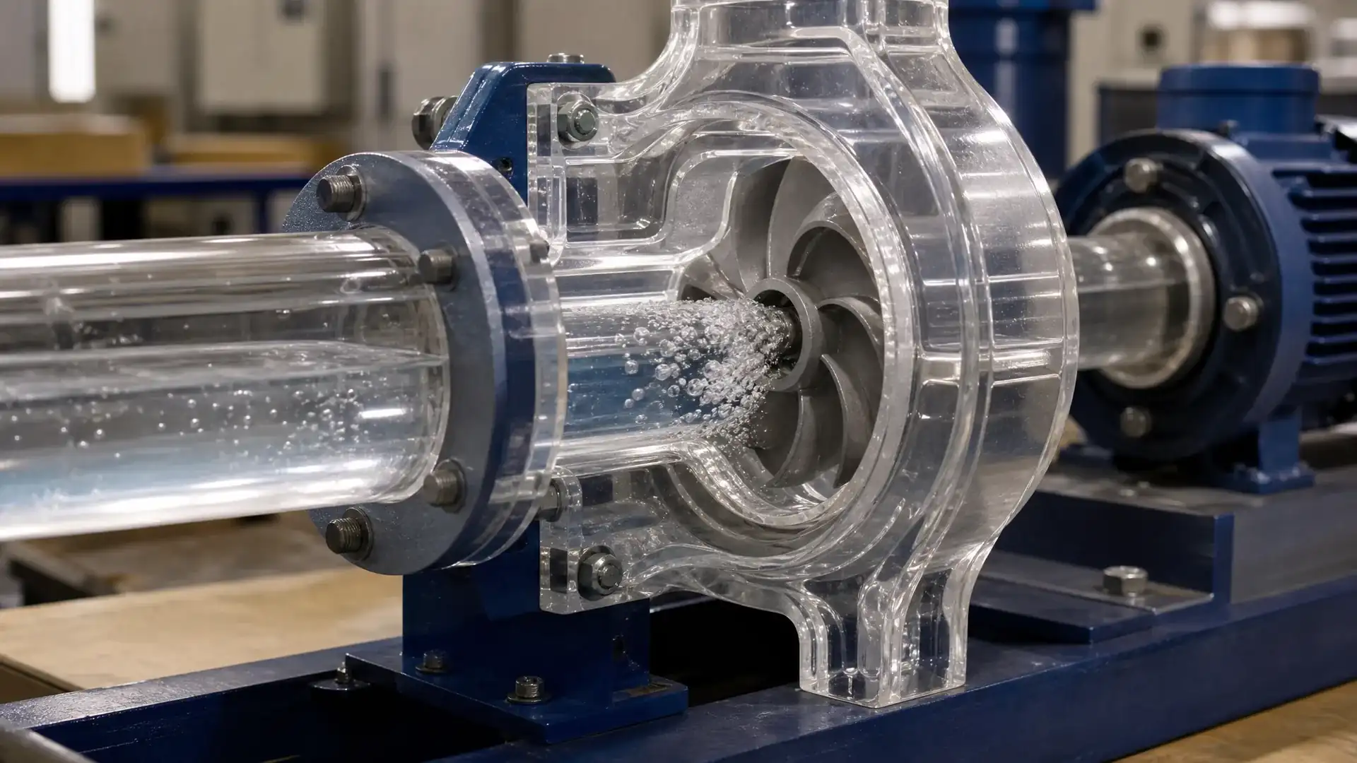
Cavitation kills inline pumps faster in commercial buildings than most operators realize, because the symptoms—progressive pitting on the impeller, rising vibration, falling discharge pressure—develop slowly and get blamed on “cheap materials” rather than suction-side mistakes.
The formula is simple: NPSH available must exceed NPSH required by a safe margin. NPSHr comes from the pump manufacturer’s curve, normally measured at a 3% head drop. NPSHa is a site calculation: atmospheric pressure (adjusted for elevation) plus suction gauge pressure (or minus lift), minus vapor pressure of the liquid at its pumping temperature, minus suction line friction losses.
Why does this trip up inline pump selections? Two reasons specific to inline designs. First, some vertical inline pumps have the impeller positioned below the suction flange inlet plane, which can create a localized low-pressure zone at startup before the casing fully primes. Second, hot-water HVAC loops push vapor pressure up: water at 200°F (93°C) has a vapor pressure of about 11.5 feet absolute (3.5 m), erasing much of the natural NPSHa margin that cold-water systems enjoy. A chilled-water system with 20+ feet of NPSHa might be fine; the same pump handling 180°F heating water in the same building may be cavitating.
Glycol mixtures—common in northern-climate HVAC freeze protection—also shift NPSH boundaries and pump curve shapes. Even a 30% ethylene glycol solution increases viscosity and slightly reduces NPSHa while the manufacturer’s NPSHr curve was developed on water. If your system runs glycol, ask the supplier to adjust performance data accordingly.
Minimum safe practice: maintain at least a 3-foot (0.9 m) NPSH margin at duty point, and verify margin at the lowest expected suction pressure condition (minimum city pressure, highest liquid temperature, worst-case strainer fouling). Hydraulic Institute and ANSI/HI pump application guidance commonly treat NPSH margin recommendations as application-dependent rather than universal pass/fail limits, so final acceptable margin must be confirmed against the supplier’s published curves, operating range, fluid properties, and actual site conditions. If the margin is smaller than that, fix the suction piping before buying the pump.
Vertical Inline Pump vs. Horizontal Inline Pump
Most buyers land on this question early, and most of the time the right answer is “it depends on your site, not on the pump catalog.” The two designs handle the same hydraulic work. The difference is how you’ll live with the pump for 20 years.
| Selection Factor | Vertical Inline Pump | Horizontal Inline Pump |
|---|---|---|
| Floor footprint | Smallest—pump occupies roughly the pipe flange area plus a surrounding clearance band | Larger—motor extends horizontally, requiring wider access aisles |
| Overhead clearance | Motor on top; need headroom for lifting during seal or bearing service | Motor at side; better for low-ceiling mechanical rooms |
| Maintenance access | Seal and bearing service typically from above; may require ladder or platform | Access from multiple sides; easier for large-motor service |
| Pipe loading risk | Higher—casing and motor mass create vertical load path through flanges | Moderate—horizontal layout distributes weight differently |
| Motor size limit | Practical up to about 60–75 HP (45–55 kW); above that, top-heavy design becomes harder to support | Higher practical limit; large-frame motors sit on horizontal axis |
| Typical building type | High-rise mechanical floors, compact boiler rooms, retrofit into tight existing plant rooms | Ground-floor plant rooms, industrial facilities, anywhere overhead access is restricted |
When Vertical Inline Pumps Are the Better Fit
If you walk into a mechanical room where floor space costs real money—high-rise plant floors, tight retrofit boiler rooms, or stacked mechanical penthouses—vertical is the default answer. The pump literally sits in the pipe run. One contractor I worked with swapped four failing baseplate end-suction pumps for vertical inline units in a 1980s district cooling plant and reclaimed enough floor space for a new plate heat exchanger skid, all without moving a single major pipe header.
But reclaiming floor space only makes sense if you keep overhead access clear. A vertical inline pump in a room with 7-foot (2.1 m) ceilings and the motor jammed against a duct is not maintainable. The motor still needs to be lifted—either with an overhead crane, a portable gantry, or at least enough clearance to slide it sideways. If the room lacks that clearance, vertical becomes a first-cost win that turns into a maintenance cost penalty every time the seal needs replacement.
Vertical inline pumps also work well in high-rise water pressure zones where pump modules stack vertically through a riser. Because the suction and discharge align with the riser direction, pipe routing is straightforward and pipe supports can be designed around axial loads.
When Horizontal Inline Pumps Make More Sense
Horizontal inline pumps win when ease of maintenance outweighs floor-space savings. The motor sits at waist or chest height, accessible from both sides without ladders. Seal changes happen within arm’s reach rather than overhead. For larger motors—say, 75 HP (55 kW) and up—horizontal layout also simplifies the structural engineering of supports and reduces the bending moments that vertical designs impose on pipe flanges.
A common scenario: a ground-floor mechanical room in a water treatment plant or a university campus central plant where floor space is generous but uptime is critical. The facility team wants a pump they can pull apart during a scheduled shutdown without rigging equipment and without shutting down adjacent equipment lines. Horizontal inline pumps deliver that.
If you need a deeper look at pump layout trade-offs beyond inline designs, review your supplier’s GA drawings alongside the maintenance-clearance checks covered earlier in this guide before committing to a final layout.
Motor Configuration and VFD Compatibility with Inline Pumps
Inline centrifugal pump selections fall apart when the motor and control strategy are treated as afterthoughts. The pump curve and the motor curve interact across the full speed range, and a VFD that “should” save energy can destroy a seal or bearing if the minimum flow line isn’t respected.
Close-Coupled vs. Flexible-Coupled Inline Pumps
Close-coupled inline pumps mount the impeller directly on an extended motor shaft. The pump casing bolts to the motor face, eliminating shaft-to-shaft alignment as a maintenance task. That reduces installation complexity and initial cost. The trade-off is that all mechanical seal heat and hydraulic thrust transfer directly to the motor bearings—the motor becomes the pump’s bearing frame. For clean, moderate-temperature HVAC water, that’s generally fine. For hotter water (above roughly 200°F/93°C) or systems with frequent start-stop cycling, close-coupled designs may accelerate bearing wear because the motor wasn’t designed as a pump thrust bearing.
Flexible-coupled inline pumps add a bearing frame between motor and pump with a shaft coupling in between. The pump’s hydraulic loads stay within the pump’s own bearings, and the motor spins freely on its own bearings. Maintenance access to the seal and impeller is better because you can pull the pump cartridge without disturbing the motor. The cost and footprint are larger; the service life in demanding applications is generally longer.
For most commercial HVAC circulation work, close-coupled is the standard pick. But if the application runs 24/7, handles water above 180°F, or involves frequent VFD speed swings, the extra cost of a flexible-coupled design often pays back in reduced seal and bearing replacements over the pump’s life. This is where a broader industrial pump selection framework helps set proper duty-cycle expectations.
VFD Selection: What Actually Matters
Adding a VFD to an inline pump changes the selection rules. A pump that runs at fixed speed can be selected near the best-efficiency flow point. A VFD-driven pump must operate stably across a speed range—typically 30 Hz to 60 Hz (in 60 Hz regions), with corresponding flow and head changes following affinity laws.
Three VFD-specific selection rules for inline pumps:
- Minimum flow at minimum speed must stay above the pump’s minimum continuous stable flow. Below this flow, internal recirculation, suction recirculation, or discharge recirculation can cause cavitation-like damage and vibration. Manufacturers don’t always publish minimum continuous flow limits clearly—ask for it specifically when VFD operation is planned. On small inline pumps, roughly 25–30% of BEP flow may serve as a conservative floor.
- The system curve, not the pump curve, determines VFD energy savings. A closed HVAC loop with mostly frictional losses sees roughly cube-law savings (half speed ≈ one-eighth power). An open-circuit booster system pumping against mostly static head sees much less savings because speed reduction quickly drops below the shutoff head needed to move water at all. This is why VFDs on HVAC circulation pumps usually pay back faster than VFDs on domestic water booster pumps.
- Motor insulation class and cooling matter at reduced speed. Standard TEFC motors cooled by a shaft-mounted fan lose cooling airflow as speed drops. Below about 20–25 Hz (for a 4-pole 60 Hz motor), winding temperature may rise enough to trip thermal protection on hot days. If your duty profile includes sustained low-speed operation, specify inverter-duty motors with Class F insulation and a 1.15 service factor minimum, or consider auxiliary cooling. For more on motor thermal management, our water-cooled vs air-cooled pump motor comparison explains when forced cooling becomes necessary.
Common Inline Pump Selection Mistakes in Commercial Buildings
I’ve seen the same six mistakes repeat across projects on three continents. They’re all preventable if you check for them before the purchase order goes out.
- Oversizing the pump for “future expansion.” Adding 20–30% extra flow capacity to a selected pump pushes the operating point far left of BEP during normal operation. The pump runs at lower efficiency, the mechanical seal sees hydraulic instability from internal recirculation, and the motor operates at a poor power factor. Future-proofing is better done by planning a parallel pump addition or selecting a VFD-capable motor that can be paired with a larger impeller trim later—not by buying a pump that’s the wrong size from day one.
- Ignoring pipe loads on vertical inline pumps. This is one of the most common causes of premature mechanical seal failures. The weight of the pipe run, water, and thermal expansion forces must be carried by independent pipe hangers within two pipe diameters of the pump flanges. Contractors sometimes omit those hangers to save cost, and the pump casing distorts enough to unseat the seal faces. If your specification doesn’t explicitly call out suction and discharge pipe supports, add it.
- Assuming NPSHr is the same at all flow rates. It isn’t. NPSHr rises sharply as flow increases past BEP. If your system demand occasionally pushes the pump into the right portion of its curve (low-head, high-flow conditions during light HVAC loading with wide-open valves), you can cavitate a pump that has plenty of NPSH margin at the design point.
- Selecting the pump before checking maintenance clearance. Put the dimensional drawing on a plan view with ladder access, lifting path, and valve handle clearance. A pump that fits inside the mechanical room on paper may be impossible to service when surrounded by ductwork, piping, and electrical panels after installation.
- Using a single pump where dual duty-standby is warranted. Circulation pumps serving critical cooling for data centers, hospital HVAC, and continuous-process cooling need N+1 redundancy. The cost of a second inline pump and check valve is minor compared to four hours of unplanned downtime during a heatwave.
- Forgetting to confirm glycol-adjusted performance. If your HVAC system runs propylene or ethylene glycol for freeze protection, the pump curve, power draw, and NPSHr shift—sometimes enough to require a different impeller diameter or one motor size up. Ask the supplier to provide performance data based on the actual fluid properties, not just water.
RFQ Checklist for Inline Pump Suppliers
A good inline pump quotation depends on complete input data. Send the list below to every bidder—if a supplier can’t or won’t answer these questions, their pump selection is guesswork.
| RFQ Data Field | Your Input / What to Confirm |
|---|---|
| Required flow (duty point) | gpm or m³/h at which the pump must achieve design head |
| Total dynamic head (duty point) | ft or m, per system friction loss calculation, including safety margins applied |
| Liquid type | Clean water / glycol-water mix (specify % and type) / hot water / other |
| Liquid temperature range | Min and max operating temperature °F or °C |
| NPSH available at pump suction | ft or m, at worst-case conditions (hot liquid, low suction pressure, fouled strainer) |
| System type | Closed HVAC loop / open booster system / other—this affects static head contribution |
| Space constraints | Maximum allowable footprint (L×W), overhead clearance height, nearby obstructions |
| Maintenance access plan | Vertical or horizontal preference; overhead lifting capability; ladder or platform available |
| Electrical supply | Voltage, phase, frequency; VFD planned or fixed-speed |
| Motor requirements | IE3/IE4 efficiency class, IP rating, insulation class, inverter-duty if VFD |
| Redundancy | N+1 duty-standby, parallel pumps, or single pump |
| Quantity per system | Number of operating pumps plus standby units |
| Documentation required | Performance curve, GA dimensional drawing, NPSHr curve, material certificates, motor data sheet, test report to ISO 9906 performance-testing grade (specify acceptance level required by the project or consultant) |
| Inspection preference | Standard factory test, witnessed test, or material inspection only |
| Packaging requirement | Sea-freight crating, export pallet, or domestic packaging; shaft bracing required |
| Target delivery timeline | As accurate as possible—affects factory scheduling and freight mode |
If your project involves high-head booster systems where single-stage inline pumps won’t reach the required pressure, you’ll need to assess multistage options. Our multistage pump selection guide for high-head water supply covers what changes when you step up from single-stage designs.
FAQ: Inline Pump Selection Questions Buyers Ask Before Ordering
These questions surface in nearly every significant inline pump procurement I’ve been involved with. Each one has a “it depends” component, so I’ve given you the conditions that determine the answer.
Can inline pumps be used in high-rise buildings?
Yes—and they’re widely used. In tall buildings, the limiting factor is pressure rating, not the inline pump concept itself. Standard ANSI Class 125 or Class 250 flanges cover many commercial pressures; when static head exceeds flange ratings, pump stations are zoned so each booster handles a pressure step the piping and pump casing are rated for. Vertical inline multistage pumps handle individual high-rise pressure zones. The bigger concern at selection stage is suction pressure into the pump: if it’s pulling from a break tank at atmospheric pressure at the base of the building, that’s fine. If it’s receiving already-pressurized city water, confirm the suction pressure does not exceed the casing’s maximum allowable working pressure. Pressure-zoning strategy drives how many pump sets you need, not whether inline pumps are suitable.
What is the preferred operating range for centrifugal inline pumps?
The Hydraulic Institute recommends operating centrifugal pumps between 70% and 120% of BEP flow for acceptable service life. Within that band, hydraulic loads are balanced, internal recirculation is minimal, and vibration stays within limits. Between 50% and 70% of BEP, pump life shortens; below 50%, continuous operation usually damages seals and bearings faster than expected. On the high-flow side, beyond 120% of BEP, NPSHr rises quickly and cavitation risk increases. If your system demand varies widely, a VFD can keep the pump in its sweet spot—but only if the minimum flow threshold is respected.
Are vertical inline pumps harder to maintain?
They’re not harder in principle—the mechanical seal and bearings are the same components. But access can be harder if the mechanical room wasn’t designed for it. A vertical inline pump motor sits on top. To change a seal, technicians may need to work overhead, disconnect piping to slide the cartridge out, or use a lifting device in a space with limited headroom. In a well-designed room with overhead clearance and a monorail, vertical inline pump maintenance is straightforward. In a cramped retrofit with no lifting access, the same pump will frustrate your maintenance team. The layout—not the pump—determines the difficulty.
When should a multistage inline pump be selected?
When TDH exceeds what a single impeller can achieve at a practical speed and diameter. A typical single-stage inline centrifugal pump maxes out around 200–260 feet (60–80 m) depending on flow. Above that, efficiency drops and impeller diameters become impractical. Multistage inline pumps stack two or more impellers in series on a common shaft to build pressure incrementally, reaching several hundred feet of head while keeping casing diameters manageable and efficiency reasonable. High-rise booster systems, long-distance water transmission, and high-pressure cleaning feed are typical applications. If your TDH is above 250 feet and your flow is moderate (below about 500 GPM), multistage is likely the right call.
Can one inline pump handle both HVAC and domestic water supply?
Almost never advisable. HVAC loops are closed systems with relatively constant flow and low static head beyond friction. Domestic water supply is an open system with variable demand, high static head if the building is tall, and different pressure requirements. Trying to serve both with one pump forces you to select for the highest pressure and widest demand variation, usually ending up with an oversized pump that cycles excessively on domestic demand and wastes energy on HVAC circulation. Separate pump sets allow you to optimize each system for its actual operating profile.
What documents should suppliers provide before I approve a pump selection?
At minimum: the pump performance curve marked with your duty point, the NPSHr curve across the flow range, a GA dimensional drawing showing overall dimensions and flange sizes, allowable pipe or nozzle load limits for the pump casing, and a motor data sheet with efficiency class and electrical characteristics. For larger or critical pumps, add material certificates for casing, impeller, and shaft materials, a hydrostatic test report, and a factory performance test report to an ISO or HI standard. If the pump will operate with a VFD, request the minimum continuous stable flow value and verify it against your minimum demand scenario.
How do I verify that the pump operates near BEP after installation?
After commissioning, measure motor power draw or install a portable flow meter during balanced operation. Compare those measured values against the pump curve at the observed discharge pressure. If power draw is significantly lower than the curve predicts, the pump is running left of BEP at lower flow—possibly throttled by a balancing valve. If power draw is at or above the curve value but discharge pressure is low, the pump may be running right of BEP at higher-than-designed flow. A pump running far off BEP may still move water, but it will cost more in energy and maintenance across the equipment’s life. Post-installation verification isn’t optional if you want to hold the supplier accountable for their selection.
Conclusion: Final Verification Before You Buy
Before you sign the purchase order, check five things:
- Duty point versus BEP: The operating point on the supplier’s marked-up curve sits between 70% and 120% of BEP flow. If it’s outside that band, ask why and what the efficiency penalty is.
- NPSH margin: NPSHa minus NPSHr is at least 0.5–1 m (1.5–3 ft) across the operating flow range, not just at the design point. Confirm the worst-case suction condition was used.
- Pipe support specification: Your installation drawings or technical specification include independent pipe supports near both pump flanges. Write it in now; retrofitting hangers after the pump is installed costs far more.
- Maintenance clearance verified: The dimensional drawing overlaid on your floor plan shows workable access for seal replacement, bearing access, and motor lifting. If the room doesn’t fit the drawing, fix the layout, not the pump.
- VFD operating envelope: If variable speed is planned, the minimum flow at minimum speed stays above the pump’s minimum continuous stable flow. The motor is inverter-duty rated and cooling is addressed.
A correctly selected inline pump can often achieve 15–20 years of service in HVAC loops and water supply systems when installation quality, water chemistry control, operating duty cycle, and maintenance practices are all managed properly. After proper sizing, the biggest influence on actual service life is installation quality and maintenance access. The selection logic above gives you a defensible basis for approving or rejecting a supplier’s pump proposal—and for knowing which questions to push back on when the answers don’t add up.
Get A Quote

Get A Quote
0 Comments