
Correct Pump Startup and Shutdown Guide: Practical SOP for Industrial Pump Users
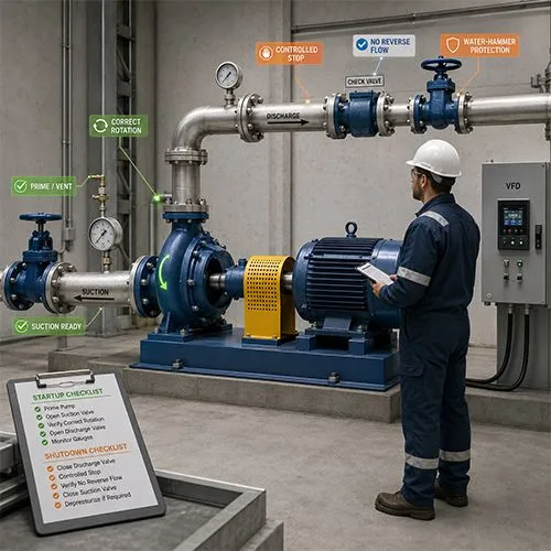
Correct pump startup and shutdown protects the pump from dry running, cavitation, water hammer, seal damage, bearing overload, motor trips, reverse flow, and avoidable commissioning disputes. For most industrial pump systems, the correct sequence is to verify suction supply, prime and vent the pump, confirm valve positions, protect the mechanical seal, verify driver readiness, start under controlled conditions, monitor flow, pressure, current, vibration, leakage, temperature, and then shut down in a way that prevents pressure shock, reverse rotation, and missing records.
A pump startup or shutdown error can damage a healthy pump in minutes. A dry mechanical seal, closed suction valve, blocked strainer, wrong rotation, deadheaded discharge, unstable VFD ramp, failed check valve, or missing minimum flow path can create failures that look like pump quality problems but are actually site operation problems.
This guide is written for operators, maintenance teams, plant engineers, commissioning engineers, pump buyers, procurement managers, EPC teams, and distributors who need a practical pump startup and shutdown procedure that can be used for SOPs, commissioning records, supplier verification, and operator training.
Quick Answer: What Is the Correct Pump Startup and Shutdown Sequence?
The correct pump startup sequence is to confirm the correct pump and service, verify suction supply, open the suction valve, prime and vent the pump casing, confirm the mechanical seal or seal support system is ready, check coupling guard and rotation direction, set the discharge valve according to pump type and system requirement, start the pump under controlled conditions, gradually bring it to duty, and monitor pressure, flow, motor current, vibration, temperature, noise, and leakage.
The correct shutdown sequence is to confirm why the pump is stopping, reduce system load if required, stop the driver through the approved control method, verify check valve closure, avoid water hammer, confirm no reverse rotation, isolate only when required, and record final operating data.
Definition: A correct pump startup and shutdown procedure is a controlled operating sequence that verifies liquid supply, priming, venting, valve position, driver readiness, rotation direction, seal protection, flow path, instrument readings, control logic, and safe stopping conditions before and after pump operation.
Standard Answer: To start and shut down a pump correctly, confirm suction supply, prime and vent the pump, protect the mechanical seal, verify valve positions, confirm rotation direction, start the motor or VFD under controlled conditions, monitor flow, pressure, current, vibration, noise, temperature, and leakage, then shut down by avoiding sudden flow reversal, water hammer, deadheading, and uncontrolled pressure changes. Record startup and shutdown readings to create a baseline for future troubleshooting.
Pump Startup vs Shutdown: Key Difference
Startup and shutdown are both transition periods, but they protect against different risks. Startup focuses on making sure the pump is ready to rotate with liquid support. Shutdown focuses on stopping flow without pressure shock, reverse flow, unsafe isolation, or missing event records.
| Action | Startup Goal | Shutdown Goal |
|---|---|---|
| Valve check | Create a safe flow path before rotation | Prevent pressure shock and reverse flow |
| Priming | Protect impeller and seal from dry running | Preserve readiness for the next start if required |
| Venting | Remove trapped air before operation | Avoid unsafe trapped pressure before maintenance |
| Control check | Prevent wrong speed, trip, or overload | Prevent sudden deceleration and water hammer |
| Seal check | Confirm liquid film, flush, or cooling before rotation | Confirm no abnormal leakage or heat after stop |
| Monitoring | Confirm pressure, flow, current, vibration, leakage | Confirm check valve closure and no reverse rotation |
| Record | Create startup baseline | Record stop reason and abnormal symptoms |
The simplest way to remember the difference is this: startup proves the pump is ready to run; shutdown proves the system has stopped safely.
30-Second Pump Startup and Shutdown Checklist
This checklist is for operators and maintenance teams who need a quick field reference. It does not replace the OEM manual, site safety procedure, or project-specific commissioning plan, but it helps prevent the most common startup and shutdown mistakes.
| Stage | What to Check | Why It Matters | Stop If Abnormal |
|---|---|---|---|
| Before startup | Pump tag, service, liquid, isolation status | Prevents wrong-pump operation | Wrong pump or wrong line selected |
| Suction side | Suction valve open, tank level, strainer clear | Prevents dry running and cavitation | No liquid supply or suction blocked |
| Pump casing | Pump primed and vented | Protects mechanical seal and impeller | Air remains in casing |
| Discharge side | Discharge valve, check valve, minimum flow path if required | Prevents deadhead, overheating, or reverse flow | Valve stuck or line blocked |
| Driver | Motor/VFD ready, correct rotation, guard installed | Prevents motor and coupling damage | Wrong rotation or exposed coupling |
| Startup | Start under controlled load | Protects pump and system | No pressure rise, abnormal noise |
| Running check | Flow, pressure, current, vibration, leakage | Confirms safe operation | Rapid vibration, leakage, high current |
| Shutdown | Stop in correct sequence and avoid pressure shock | Prevents water hammer and reverse flow | Check valve slam or reverse rotation |
| After shutdown | Record final condition | Supports troubleshooting and warranty | No record after abnormal event |
The key rule is simple: never start a pump unless the pump casing, suction line, and seal area are ready for liquid-supported operation.
Scope of This Guide: Which Pump Systems Does This Apply To?
This guide applies mainly to industrial and commercial pump systems where startup and shutdown errors can affect pump reliability, mechanical seal life, bearing condition, motor protection, piping safety, and system performance. It is most useful for centrifugal pumps, including end suction pumps, split case pumps, inline pumps, multistage pumps, booster pump packages, cooling water pumps, chilled water pumps, process water pumps, irrigation pumps, municipal transfer pumps, and general industrial utility pumps.
The same principles also help with submersible sewage pumps, slurry pumps, vertical turbine pumps, chemical pumps, and fire pump-related systems, but the exact sequence must be adjusted for installation method, liquid hazard, solids content, control logic, and local code requirements.
Applicable Pump Types
Different pump types require different startup emphasis. A single startup SOP should not be copied blindly across every pump in a plant.
| Pump Type | Startup Focus | Shutdown Focus | Main Risk |
|---|---|---|---|
| End suction pump | Priming, suction valve, rotation, seal condition | Avoid reverse flow and seal overheating | Dry running, cavitation, seal leakage |
| Split case pump | Bearing lubrication, flow path, casing venting | Avoid water hammer and bearing heat | Vibration and bearing damage |
| Multistage pump | Minimum flow, seal cooling, pressure rise control | Avoid deadhead and thermal stress | Overheating and high-pressure seal damage |
| Inline pump | Valve position, pipe strain, motor condition | Avoid sudden pressure changes | Pipe stress and vibration |
| Booster package | Sensor signal, VFD ramp, lead/lag sequence | Prevent pressure surge and short cycling | Control instability |
| Submersible sewage pump | Liquid level, cable, level control, pump submergence | Prevent dry running and clogging | Motor overheating and seal chamber failure |
| Slurry pump | Flush water, solids suspension, liner/impeller condition | Flush line before shutdown if required | Abrasive wear and blockage |
| Chemical pump | Isolation, containment, seal plan, PPE | Safe depressurization and containment | Hazardous leakage |
| Vertical turbine pump | Water level, column filling, motor rotation | Avoid reverse rotation and column surge | Low water level and line shaft stress |
Use With Adjustment
Use this guide with adjustment for hazardous chemicals, explosive areas, high-temperature liquids, high-pressure boiler feed systems, fire pumps, sanitary pumps, API process pumps, and regulated safety systems. In these cases, site-specific procedures, OEM instructions, project specifications, and applicable safety rules must override any general guide.
Submersible pumps should not be treated like dry-installed horizontal pumps. Their startup readiness depends on liquid level, submergence, cooling condition, cable condition, level switch function, dry-run protection, and seal chamber monitoring rather than manual priming in the same way as surface pumps.
For hazardous chemical service, venting and draining must be routed to a safe containment, recovery, or treatment system. Operators should not open vents or drains directly to the work area unless the site procedure confirms that the liquid and vapor are safe to release.
Why Pump Startup and Shutdown Mistakes Cause Early Failure
Pump startup and shutdown mistakes damage pumps because the rotating assembly, seal faces, bearings, valves, motor, and piping experience unstable conditions before normal flow is established or after flow is interrupted. A pump is designed to operate within a defined hydraulic and mechanical envelope. Startup and shutdown are transition periods where mistakes can push the pump outside that envelope.
The most common failures are dry-running mechanical seals, cavitation from poor suction, deadheading against a closed discharge path, motor overload from wrong valve position, water hammer after sudden stop, reverse rotation after check valve failure, and repeated VFD trips caused by wrong acceleration or control logic.
| Startup or Shutdown Mistake | Likely Damage | First Area to Check |
|---|---|---|
| Starting without priming | Mechanical seal damage, no flow | Pump casing, vent, suction supply |
| Starting with suction valve closed | Cavitation, dry running, overheating | Suction valve and tank level |
| Wrong rotation direction | Low flow, vibration, impeller damage | Motor wiring and rotation arrow |
| Starting against blocked discharge | Deadhead heat and pressure rise | Discharge valve and downstream line |
| No minimum flow on multistage pump | Overheating and seal stress | Minimum flow bypass |
| Sudden shutdown at high flow | Water hammer and check valve slam | Check valve and shutdown sequence |
| Failed check valve | Reverse flow and reverse rotation | Check valve and discharge pressure |
| VFD ramp too aggressive | Pressure surge or trip | Ramp time and setpoint |
| No post-startup record | Future diagnosis impossible | Startup log |
A good startup and shutdown guide prevents damage by forcing the operator to verify the system before the pump is exposed to load. For users dealing with seal leakage after startup, this pump seal leak troubleshooting guide can help separate dry start, seal support, suction instability, and installation causes.
Startup Abnormal Symptoms: Stop Immediately or Continue Monitoring?
Startup problems must be judged quickly. Some symptoms can be monitored briefly during stabilization, but others require immediate stop because continued operation may damage the seal, bearings, impeller, motor, or piping.
This table gives operators a practical first response. Site safety rules, OEM limits, alarm settings, and process requirements should always take priority.
| Startup Symptom | Likely Risk | Stop Immediately? | First Check |
|---|---|---|---|
| No discharge pressure rise | No prime, wrong rotation, blocked discharge | Yes | Priming, rotation, discharge valve |
| Suction pressure drops sharply | Suction blockage, low tank level, cavitation | Usually yes | Suction valve, strainer, tank level |
| Loud gravel-like noise | Cavitation | Yes if severe | NPSH, suction pressure, air ingress |
| Seal area becomes hot | Dry running or no flush | Yes | Priming, seal flush, venting |
| Motor current too high | Overload, wrong valve position, wrong duty | Yes if above limit | Valve position, voltage, duty point |
| Severe vibration | Misalignment, cavitation, bearing issue | Yes | Coupling, bearing, suction condition |
| VFD trips repeatedly | Electrical or hydraulic instability | Do not keep restarting | Alarm code, ramp, sensor, load |
| Leakage spray near coupling or motor | Unsafe seal or flange leakage | Yes | Seal area, pressure, isolation |
| Bearing temperature rises quickly | Lubrication, misalignment, overload | Yes if rapid or above site limit | Lubrication, alignment, vibration |
| Check valve slams during start/stop transfer | Reverse flow or valve issue | Stop and inspect if repeated | Check valve, sequencing, pressure |
Do not repeatedly restart a pump after a trip without finding the cause. Repeated starts can worsen seal damage, motor heating, and hydraulic shock.

Pump Startup Procedure: Step-by-Step Checklist Before Pressing Start
A correct pump startup procedure should move from safety confirmation to liquid confirmation, then from mechanical readiness to controlled startup and operating verification. Operators should not jump directly from “power available” to “start pump.”
The procedure below is written for a typical industrial centrifugal pump. Site-specific lockout rules, OEM instructions, control philosophy, and project requirements should always be followed.
Step 1: Confirm the Pump, Line and Service
Before startup, confirm the correct pump tag, liquid service, suction source, discharge destination, and operating mode. This avoids starting the wrong pump or sending liquid to the wrong process line.
Check the nameplate, pump tag, control panel tag, valve labels, and process instruction. If multiple pumps are installed in a parallel system, confirm which unit is duty, standby, or under maintenance.
Step 2: Confirm Safety and Mechanical Readiness
The pump should not be started if coupling guards are missing, baseplate bolts are loose, leakage is unsafe, piping is unsupported, or maintenance tools remain near rotating parts.
Check the coupling guard, bearing housing, baseplate, anchor bolts, motor fan cover, drain area, and nearby personnel access. A safe pump startup is both a mechanical action and a site safety action.
Step 3: Confirm Suction Supply
Most startup failures begin on the suction side. The suction valve should normally be fully open before startup for centrifugal pumps. The tank level, suction pressure, suction strainer, and suction line condition should be checked before the motor is energized.
If the suction side is restricted, the pump may cavitate, lose prime, run dry, or fail to build pressure. For lift applications or self-priming arrangements, confirm the priming method before start.
Step 4: Prime and Vent the Pump
Priming means filling the pump casing and suction line with liquid so that the impeller and mechanical seal are not running in air. Venting removes trapped air from the pump casing or high points where air can block flow.
Do not assume the pump is primed just because the suction valve is open. Open the vent if required, confirm liquid reaches the vent point safely, and close the vent according to site procedure.
Step 5: Protect the Mechanical Seal
A mechanical seal needs a liquid film between the seal faces. If the seal chamber is dry or the flush line is blocked, the seal can be damaged quickly after startup.
Before startup, check seal leakage condition, flush flow if applicable, seal cooling, barrier or buffer fluid level if applicable, and any seal support system. For repeated seal leakage problems, this mechanical seal life extension guide explains how dry running, flush quality, suction instability, and vibration affect seal life.
Step 6: Confirm Discharge Path and Valve Position
The discharge valve position depends on pump type, system design, control method, and OEM recommendation. Some centrifugal pumps are started with the discharge valve closed or partially open to reduce starting load, then the valve is opened gradually. However, some systems require an open discharge path, a minimum flow line, or a specific control valve position.
Do not use “start with discharge valve closed” as a universal rule. Some pumps or systems require minimum flow, bypass flow, or an open discharge path before startup.
Step 7: Confirm Driver and Control Readiness
Check motor power, VFD status, starter condition, control mode, interlocks, alarm history, emergency stop, and rotation direction. Wrong rotation can cause low flow, vibration, overheating, and impeller or coupling stress.
For VFD-controlled pumps, confirm speed reference, ramp time, minimum frequency, maximum frequency, pressure sensor signal, and lead/lag logic if the pump is part of a booster or multi-pump package.
Step 8: Start the Pump and Monitor Immediate Response
After starting, the pump should build pressure smoothly and begin moving flow according to system demand. Operators should watch suction pressure, discharge pressure, motor current, vibration, noise, leakage, and VFD alarms during the first minutes.
If there is no pressure rise, abnormal noise, severe vibration, rapid leakage, high current, or no flow, stop and investigate. Do not keep a pump running to “see if it improves” when the symptoms suggest dry running, blocked suction, wrong rotation, or deadhead.
Step 9: Bring the Pump to Normal Duty
Once the pump starts safely, bring the system to normal operating duty gradually. Adjust discharge valve, VFD speed, control setpoint, or process demand according to the system design.
Record flow, suction pressure, discharge pressure, motor current, vibration, bearing temperature, seal leakage, and control status. This creates the startup baseline for future troubleshooting.
Centrifugal Pump Startup Procedure: What Should Be Open or Closed?
One of the most common startup questions is whether the suction valve, discharge valve, bypass valve, and minimum flow line should be open or closed. The answer depends on pump type, system design, and service condition.
For most centrifugal pumps, the suction valve should be open before startup. The discharge-side position must follow the pump and system requirement, not a universal rule.
| Item | Typical Startup Position | Why | Important Boundary |
|---|---|---|---|
| Suction valve | Open | Prevents starvation and dry running | Do not start with suction valve closed |
| Pump casing vent | Open during venting, closed before running if required | Removes trapped air | Chemical service must vent to safe containment |
| Discharge valve | Closed, partially open, or open depending on system | Controls starting load and flow path | Do not apply one rule to all pumps |
| Minimum flow line | Open if required | Prevents overheating at low flow | Critical for many multistage/high-head pumps |
| Seal flush line | Open/active if required | Protects seal faces | Must be verified before start |
| Bypass line | As defined by SOP | Supports minimum flow or control logic | Avoid unintended energy waste |
| Check valve | Ready and functional | Prevents reverse flow | Must not be stuck or installed backward |
| Drain valve | Closed before startup | Prevents loss of liquid | Confirm safe closure after maintenance |
The safest SOP is the one that names the actual valve tag, required position, and reason. “Open as needed” is usually too vague for critical pumps.
Minimum Flow Protection: Why Some Pumps Should Not Run at Closed Discharge
Minimum flow protection is essential for many high-head, multistage, boiler feed, process, and critical service pumps. When flow is too low, the liquid inside the pump can heat up, internal recirculation can increase, the seal chamber can overheat, and vibration may rise.
A short closed-discharge start may be acceptable for some centrifugal pumps under specific procedures, but it should not be treated as a universal rule. Pumps with minimum continuous stable flow requirements need a bypass, recirculation line, automatic minimum flow valve, or another verified flow path.
| Pump/System Condition | Minimum Flow Risk | What to Verify |
|---|---|---|
| Multistage pump | Internal heat and high-pressure seal stress | Minimum flow line or automatic recirculation |
| Boiler feed/high-head pump | Rapid temperature rise at low flow | Minimum continuous stable flow requirement |
| VFD pump at very low speed | Poor cooling or unstable control | Minimum frequency and flow limit |
| Closed discharge during start | Deadhead heat if held too long | Maximum allowed closed-valve time |
| Process pump with hot liquid | Seal chamber overheating | Cooling/flush and minimum flow path |
| Standby pump in auto mode | Short cycling and low-flow operation | Control logic and lead/lag sequence |
| Pump with mechanical seal support | Seal face heat | Flush or barrier support before start |
Buyers should ask the supplier to state the minimum flow requirement clearly in the manual, commissioning checklist, and RFQ response. If the pump datasheet does not clarify minimum flow, the site team should not assume that closed-discharge operation is safe.
First Startup, Routine Startup, and Restart After Maintenance: What Changes?
Not every startup has the same risk. First startup verifies installation quality. Routine startup verifies operating readiness. Restart after maintenance verifies whether the repair was successful and whether the pump was reassembled correctly.
A good SOP should separate these cases instead of using one generic checklist for all starts.
| Startup Type | Extra Checks Required | Why It Matters |
|---|---|---|
| First startup / commissioning | Rotation, alignment, foundation, grout, valve direction, instrument calibration, baseline record | Prevents installation-related failure |
| Routine startup | Suction supply, priming, valve position, control status, normal alarms | Prevents operator error |
| Restart after seal replacement | Seal chamber liquid, flush, leakage, vibration baseline | Prevents immediate seal failure |
| Restart after bearing or motor service | Alignment, bearing temperature, motor current, rotation | Prevents rotating assembly damage |
| Restart after long standby | Lubrication, stuck valve, casing fill, insulation if required, control readiness | Prevents dry, seized, or failed-start condition |
| Restart after VFD setting change | Ramp, minimum frequency, setpoint, sensor signal, alarm history | Prevents trips and unstable pressure |
| Restart after pipeline maintenance | Valve direction, flange leakage, air pockets, debris, strainer condition | Prevents blockage and trapped air |
| Emergency restart | Safety status, process risk, standby status, alarm cause | Prevents repeated failure under unsafe condition |
This table is especially useful for training. Operators often understand routine starts but miss the extra checks required after maintenance or commissioning.
Pump Startup Checklist by Component
A component-based checklist helps operators avoid missing small details. It also helps buyers and project teams define what should be included in a commissioning record.
This table can be adapted into a field checklist or mobile inspection form.
| Component or Area | Startup Check | Normal Condition | Action If Abnormal |
|---|---|---|---|
| Pump casing | Primed and vented | Liquid present, air removed | Do not start until primed |
| Suction valve | Open as required | Fully open for most centrifugal pumps | Confirm valve status |
| Suction strainer | Clear or acceptable pressure drop | No blockage indication | Clean before startup |
| Suction pressure | Stable | Within expected range | Check tank level or restriction |
| Mechanical seal | Wet, cooled or flushed if required | No abnormal leakage | Check seal support |
| Bearing housing | Lubricated | Oil/grease condition normal | Correct lubrication |
| Coupling guard | Installed and secure | No exposed rotating parts | Do not start if unsafe |
| Motor | Ready | No abnormal alarm or damage | Check electrical system |
| Rotation | Correct direction | Matches pump arrow | Correct wiring before operation |
| Discharge valve | Correct starting position | Matches SOP | Adjust before startup |
| Check valve | Installed and functional | No reverse flow risk | Inspect if stuck |
| Flow meter | Ready | Reading available if installed | Verify instrument |
| VFD/control panel | Ready | No active fault | Clear and investigate alarms |
| Baseplate/foundation | Stable | No loose bolts or soft foot signs | Correct before running |
The checklist should be short enough for operators to use but specific enough to prevent vague “pump checked” records.

Pump Shutdown Procedure: How to Stop a Pump Without Water Hammer or Reverse Flow
Correct pump shutdown is as important as startup. A poor shutdown can create water hammer, reverse flow, reverse rotation, check valve slam, seal heat, pressure shock, or unsafe liquid release.
Shutdown should reduce system risk, protect the pump, and create a final operating record. The correct sequence depends on pump type, system pressure, driver type, control method, and process requirement.
Step 1: Confirm Why the Pump Is Being Stopped
Before shutdown, confirm whether the stop is normal, planned, emergency, process-driven, maintenance-related, or caused by an alarm. The reason affects whether the operator should reduce load first, switch to standby pump, isolate the pump, or stop immediately.
For critical systems, stopping a duty pump without confirming standby capacity can create process interruption, pressure loss, or flooding risk.
Step 2: Stabilize the System Before Stopping
If the system allows, reduce flow or pressure gradually before stopping. This is especially important in long pipelines, high-head systems, booster systems, cooling circuits, and applications with large liquid columns.
A sudden stop at high flow can create pressure waves that damage valves, supports, gauges, and pump components.
Step 3: Stop the Driver According to Control Method
For fixed-speed motors, stop the motor through the approved starter or control panel. For VFD systems, use the programmed stop sequence unless emergency stop is required.
For diesel engine-driven or special process pumps, follow the driver-specific shutdown sequence. Do not treat every driver like a simple electric motor.
Step 4: Confirm Check Valve Closure and No Reverse Rotation
After stopping, confirm the check valve closes correctly and the pump does not rotate backward. Reverse flow can damage the pump, coupling, motor, or driver. A loud check valve slam suggests hydraulic shock or valve problem.
If reverse rotation occurs, the discharge check valve, discharge pressure condition, and shutdown sequence should be inspected.
Step 5: Close Valves Only When Appropriate
Do not close suction and discharge valves blindly after every shutdown. Valve closure depends on process requirement, maintenance need, safety isolation, standby operation, and site SOP.
If the pump is being isolated for maintenance, follow lockout, depressurization, draining, and safety procedures. If the pump is a standby unit, the valve position must match the system’s standby philosophy.
Step 6: Record Final Readings and Abnormal Symptoms
After shutdown, record final pressure, flow if available, motor current before stop, vibration, noise, leakage, bearing temperature, seal condition, VFD alarms, check valve behavior, and reason for stopping.
This record helps determine whether a later failure came from startup, running condition, or shutdown event.
Pump Shutdown Checklist by Risk
Shutdown risk is often underestimated because the pump is no longer running. In reality, the fluid system is still moving, pressure is changing, valves are closing, and liquid columns may reverse.
This checklist helps operators focus on what can go wrong during stopping.
| Shutdown Risk | Warning Sign | Possible Cause | Corrective Direction |
|---|---|---|---|
| Water hammer | Loud bang, pipe movement | Sudden stop, fast valve closure | Adjust shutdown sequence or valve timing |
| Reverse flow | Pump rotates backward | Check valve failure or slow closure | Inspect check valve |
| Seal heat after stop | Hot seal area | No cooling or low-flow heat before stop | Review flush and cooling |
| VFD trip during stop | Fault alarm | Ramp issue or regenerative load | Review VFD settings |
| Check valve slam | Loud closing impact | Oversized valve or high reverse flow | Inspect valve sizing and condition |
| Pressure collapse | Downstream pressure drops quickly | No standby pump or wrong sequencing | Review lead/lag logic |
| Leakage after shutdown | Seal or flange leakage | Pressure shock or thermal movement | Inspect leakage source |
| Motor reverse rotation | Shaft rotates backward after stop | Reverse flow through pump | Check discharge valve and check valve |
| Unsafe isolation | Liquid remains pressurized | Valve sequence or drain issue | Follow lockout and depressurization |
A controlled shutdown protects both the pump and the piping system. It also protects the next startup, because many restart failures begin with the previous shutdown.
Water Hammer and Reverse Flow: Why Shutdown Sequence Matters
Water hammer is a pressure surge caused by a rapid change in flow velocity. In pump systems, it can happen after sudden power loss, fast valve closure, rapid VFD deceleration, check valve slam, or abrupt pump stop in a long pipeline.
Reverse flow occurs when discharge-side liquid flows back through the pump after shutdown. It can cause reverse rotation, coupling stress, motor stress, and repeated check valve impact.
| Risk Factor | Why It Matters | Practical Control |
|---|---|---|
| Long discharge pipeline | Larger liquid column stores more energy | Use controlled stop and surge review |
| High flow rate | Higher momentum creates stronger pressure wave | Avoid sudden closure where possible |
| Fast-closing valve | Rapid flow interruption | Use suitable valve timing |
| Sudden power loss | Pump stops before flow stabilizes | Check surge protection and check valve behavior |
| Check valve slam | Creates impact and pressure shock | Review check valve type and condition |
| VFD deceleration too fast | Can create pressure instability | Tune ramp-down time |
| No surge control | System absorbs the pressure wave | Evaluate surge vessel, air valve, or control strategy |
| Reverse flow through pump | Reverse rotation and mechanical stress | Inspect check valve and sequencing |
For high-risk systems, water hammer prevention should be reviewed during design, commissioning, and SOP development, not only after a failure.

Pump Startup and Shutdown Procedure by Pump Type
Not every pump should be started or stopped the same way. Pump type, head, liquid, control mode, and service duty change the sequence.
A startup guide should define the normal procedure for each pump class in the plant.
| Pump Type | Startup Difference | Shutdown Difference | Buyer/Operator Note |
|---|---|---|---|
| End suction pump | Confirm priming, suction valve, rotation | Confirm check valve and leakage | Simple but vulnerable to dry running |
| Multistage pump | Confirm minimum flow and pressure rise | Avoid deadhead and thermal stress | Minimum flow protection is critical |
| Booster pump package | Confirm sensors, VFD, lead/lag logic | Avoid pressure surge and cycling | Control logic matters as much as pump |
| Split case pump | Confirm lubrication and smooth flow | Avoid water hammer in large flow systems | Large flow can create pipe shock |
| Submersible pump | Confirm liquid level and level switch | Avoid dry running after level drop | Cooling depends on submergence |
| Slurry pump | Confirm flush and solids suspension | Flush or clean before stop if required | Solids settling can block restart |
| Chemical pump | Confirm seal plan, containment, PPE | Depressurize and isolate safely | Safety procedure controls the sequence |
| Vertical turbine pump | Confirm water level and column condition | Avoid reverse rotation and surge | Low water level is a major risk |
A plant should have a general pump operating standard plus pump-specific startup and shutdown notes for critical equipment.
Startup and Shutdown Guide for VFD-Controlled Pumps
A VFD, or Variable Frequency Drive, controls motor speed by changing frequency. It can reduce pressure shock and energy use when applied correctly, but wrong settings can create unstable pressure, low-flow overheating, repeated trips, or poor lead/lag sequencing.
For VFD-controlled pumps, startup and shutdown should verify control logic, not only mechanical readiness.
| VFD Item | Startup Check | Shutdown Check |
|---|---|---|
| Control mode | Auto/manual/local/remote status | Confirm correct stop command |
| Speed reference | Setpoint, pressure sensor, level signal | No unstable signal during stop |
| Ramp time | Not too aggressive for system | Avoid sudden deceleration shock |
| Minimum frequency | Enough for cooling or minimum flow | Avoid prolonged low-flow heating |
| Maximum frequency | Within pump and motor limits | Prevent overspeed operation |
| Alarms | No active overcurrent, underload, sensor fault | Record trip cause |
| Lead/lag logic | Correct duty/standby sequence | Standby pump available if needed |
| Dry-run protection | Underload or level protection active | Prevent restart into dry condition |
| Pressure sensor | Stable and reasonable reading | Avoid control hunting |
| Bypass mode | Confirm if allowed | Avoid uncontrolled operation |
For buyers comparing fixed-speed and variable-speed control, this VFD vs fixed speed energy comparison guide explains when VFD control can reduce energy cost and when incorrect control may create reliability problems.
Mechanical Seal, Bearing and Motor Checks During Startup
Startup is a critical moment for the mechanical seal, bearings, and motor. These components reveal early symptoms quickly if the pump is not ready.
Operators should monitor these items closely during the first minutes after startup and after any repair.
| Component | What to Watch During Startup | What It May Mean |
|---|---|---|
| Mechanical seal | Immediate leakage, dry heat, spray | Dry start, poor installation, wrong seal plan |
| Bearing housing | Rapid temperature rise or noise | Lubrication issue, misalignment, bearing damage |
| Coupling | Noise, vibration, visible movement | Misalignment or coupling wear |
| Motor | High current, trip, abnormal heat | Overload, wrong rotation, voltage issue |
| Pump casing | No pressure rise, overheating | No prime, blocked discharge, wrong rotation |
| Suction gauge | Low or fluctuating pressure | Cavitation, clogged strainer, low tank level |
| Discharge gauge | No rise or unstable pressure | Wrong rotation, air, blocked system |
| VFD panel | Overcurrent, underload, sensor alarm | Control or hydraulic issue |
If a new pump or repaired pump shows abnormal seal leakage, vibration, or current during startup, stop and investigate before continuing operation. For startup vibration or bearing temperature problems, this pump bearing failure diagnosis guide can help separate lubrication, alignment, bearing wear, and hydraulic causes.
Common Startup Mistakes and How to Prevent Them
Most startup failures are preventable. They happen because operators follow habit instead of a checklist, or because the commissioning team never created a clear field procedure.
The following table can be used for operator training.
| Startup Mistake | Failure Risk | Prevention |
|---|---|---|
| Starting without priming | Dry seal and no flow | Confirm liquid at vent point |
| Starting with suction valve closed | Cavitation and overheating | Verify suction valve position |
| Ignoring strainer blockage | Low suction pressure | Check pressure drop or cleaning status |
| Wrong motor rotation | Low flow and vibration | Bump test before operation |
| Starting with no discharge path | Deadhead heat | Confirm valve and line status |
| Ignoring minimum flow | Pump overheating | Verify bypass or process flow |
| No seal flush check | Seal face damage | Confirm flush before start |
| No vibration observation | Bearing or alignment issue missed | Monitor first minutes |
| No startup record | No baseline for diagnosis | Record readings after stabilization |
| Using same SOP for every pump | Wrong sequence | Adjust by pump type and system |
A checklist should be visible near critical pumps or included in the operator control procedure.
Common Shutdown Mistakes and How to Prevent Them
Shutdown mistakes can damage pumps even after a successful running period. The most common problems are sudden pressure changes, uncontrolled reverse flow, poor isolation, and failure to record abnormal symptoms.
A shutdown SOP should define normal stop, emergency stop, maintenance isolation, and standby transfer separately.
| Shutdown Mistake | Failure Risk | Prevention |
|---|---|---|
| Sudden stop in high-flow line | Water hammer | Use controlled shutdown if possible |
| Closing valve too fast | Pressure surge | Follow valve timing procedure |
| Ignoring check valve slam | Reverse flow damage | Inspect check valve |
| Isolating pump while pressurized | Safety hazard | Depressurize and drain correctly |
| Stopping duty pump without standby | Process interruption | Confirm standby capacity |
| No post-stop observation | Reverse rotation missed | Watch shaft and pressure |
| No alarm record | Root cause lost | Record VFD/control alarm |
| Leaving pump dry for standby | Seal risk on restart | Follow standby preservation procedure |
| Not flushing dirty service | Blockage on restart | Flush or clean if required |
| No shutdown log | Cannot prove event sequence | Record final condition |
A controlled shutdown protects the next startup. Many restart failures begin with the previous shutdown.

Commissioning Record: What to Record After Startup and Shutdown
Startup and shutdown records protect both the buyer and the supplier. Without records, it becomes difficult to prove whether a failure came from manufacturing, installation, operation, control settings, or maintenance.
A commissioning record should be simple, consistent, and attached to the pump tag or project file.
| Record Item | Why It Matters |
|---|---|
| Pump tag and model | Identifies equipment |
| Date and operator | Creates accountability |
| Liquid and service | Confirms duty |
| Startup reason | Normal, test, after maintenance, emergency restart |
| Suction pressure | Verifies inlet condition |
| Discharge pressure | Verifies system head |
| Flow rate | Confirms useful output |
| Motor current | Verifies load |
| VFD frequency | Confirms speed |
| Vibration | Confirms mechanical condition |
| Bearing temperature | Tracks bearing health |
| Seal leakage | Tracks seal condition |
| Valve positions | Explains system behavior |
| Alarm history | Captures control problems |
| Shutdown reason | Normal, trip, alarm, maintenance, process stop |
| Check valve behavior | Detects reverse flow risk |
| Abnormal symptoms | Supports root cause analysis |
| Photos of gauges/control panel if critical | Preserves evidence for warranty or dispute review |
For critical pumps, the record should include photos of gauges, VFD screen, valve positions, and any abnormal leakage or vibration observations.
Post-Startup Acceptance Checklist
Startup is not complete until the pump has reached stable operation and the readings are acceptable. A pump that starts but runs with high vibration, unstable pressure, low flow, or abnormal leakage should not be accepted as normal.
The post-startup acceptance checklist should be used after new installation, repair, seal replacement, bearing replacement, motor service, VFD adjustment, or system modification.
| Acceptance Item | Acceptable Result |
|---|---|
| Suction pressure | Stable and within expected range |
| Discharge pressure | Matches system requirement |
| Flow | Meets required duty |
| Motor current | Within expected range |
| VFD frequency | Matches control demand |
| Vibration | Stable and not above site limit |
| Bearing temperature | Stable after running |
| Mechanical seal leakage | Normal for seal type and service |
| Noise | No cavitation, grinding, rubbing, or knocking |
| Check valve | No slam or reverse flow |
| Baseplate | No abnormal movement |
| Coupling guard | Installed and secure |
| Control alarms | No active fault |
| Record | Completed and saved |
For many industrial systems, acceptance should be checked after a short stabilization period, such as 5–15 minutes or a site-defined running period. The correct stabilization time depends on pump size, liquid temperature, process demand, and site procedure.
When NOT to Start or Continue Running the Pump
Some conditions require immediate stop or delayed startup. Continuing to run the pump may cause greater damage than stopping.
Operators should not start or continue operation when:
- the pump is not primed;
- suction valve is closed or suction source is unavailable;
- mechanical seal area is dry or overheating;
- seal support system is not available when required;
- rotation direction is wrong;
- coupling guard is missing;
- motor current exceeds safe range;
- discharge pressure does not rise after startup;
- cavitation noise is severe;
- vibration increases rapidly;
- bearing temperature rises quickly;
- hazardous liquid leakage is present;
- VFD or protection system shows critical alarm;
- check valve fails and reverse flow is observed.
The stop decision should follow site safety rules. For critical systems, stopping one pump may require starting standby equipment or notifying operations first.
Supplier Verification: What Should Buyers Ask About Startup and Shutdown?
Buyers should ask pump suppliers for startup and shutdown guidance before delivery, not after failure. A professional supplier should provide instructions that match pump type, seal arrangement, driver, control system, and service duty.
This is especially important for high-pressure pumps, VFD systems, mechanical seal support systems, chemical pumps, slurry pumps, and packaged pump stations.
| Supplier Question | Why It Matters |
|---|---|
| What is the correct startup valve position? | Avoids deadhead or overload |
| Does the pump require priming before every start? | Prevents dry running |
| Where is the vent point? | Prevents trapped air |
| Is minimum flow required? | Protects pump from overheating |
| What is the minimum continuous stable flow? | Prevents low-flow damage |
| What seal flush or cooling must be active before start? | Protects mechanical seal |
| What is the correct rotation direction? | Prevents low flow and damage |
| What readings should be recorded after startup? | Creates baseline |
| What VFD ramp time and speed limits are recommended? | Prevents pressure shock and trips |
| What shutdown sequence prevents water hammer? | Protects valves and piping |
| What shutdown valve timing is recommended? | Reduces pressure surge risk |
| What check valve type and position are recommended? | Reduces reverse flow risk |
| How should standby pumps be preserved? | Protects future startup |
| What conditions require immediate stop? | Prevents severe failure |
| What records are needed for warranty support? | Clarifies responsibility |
A startup and shutdown guide should be part of the technical documentation package, not an informal verbal instruction.
RFQ Checklist for Pump Startup and Shutdown Support
A clear RFQ helps the supplier provide proper startup and shutdown instructions. If the buyer only asks for pump price, important operating details may be missed.
Buyers should include:
- pump type and model;
- liquid type, temperature, solids, viscosity, and corrosiveness;
- required flow and head;
- suction source and suction pressure;
- discharge pressure and pipeline length;
- valve arrangement;
- recommended startup valve position request;
- check valve type and location;
- mechanical seal type and seal support system;
- motor type and power;
- fixed-speed, soft starter, or VFD control;
- recommended VFD ramp and speed limit request;
- control mode, sensor location, and setpoint;
- duty/standby arrangement;
- minimum flow requirement;
- minimum continuous stable flow request;
- priming method;
- site elevation and tank level if suction is sensitive;
- expected start-stop frequency;
- emergency shutdown requirement;
- shutdown valve timing request;
- required commissioning support;
- required startup report template;
- required operator training material;
- warranty documentation requirements.
The RFQ should ask the supplier to provide a written startup and shutdown procedure, not only a pump datasheet.
Best Startup and Shutdown Practice by Scenario
Different operating scenarios need different priorities. This table helps operators and buyers avoid one-size-fits-all startup habits.
| Scenario | Best Practice | Why |
|---|---|---|
| New pump commissioning | Start only after priming, rotation check, valve verification, and baseline record | Prevents early damage and creates acceptance evidence |
| After seal replacement | Confirm seal chamber liquid and flush before start | Prevents dry seal damage |
| After long standby | Inspect lubrication, rotation, valve status, and casing fill | Prevents stuck or dry-start failures |
| VFD pressure booster | Verify sensor, ramp, setpoint, and lead/lag sequence | Prevents hunting and pressure surge |
| High-head multistage pump | Confirm minimum flow and pressure rise | Prevents overheating and seal stress |
| Dirty water or slurry | Confirm flush, no settling, and open flow path | Prevents blockage and abrasive startup |
| Chemical service | Confirm containment, PPE, venting, and seal plan | Protects personnel and environment |
| Long discharge pipeline | Use controlled stop and check valve verification | Reduces water hammer |
| Parallel pump operation | Confirm sequencing and check valve behavior | Prevents reverse flow |
| Emergency stop | Follow safety priority first, then record event | Protects people and evidence |
The best procedure is the one that protects the pump under the real site condition, not the one that looks simplest on paper.
Common Mistakes in Pump Startup and Shutdown SOPs
Many pump SOPs fail because they are too vague. A statement like “start pump normally” does not help operators avoid dry running, cavitation, wrong valve position, or reverse flow.
A good SOP should be specific, measurable, and connected to real components.
| Weak SOP Wording | Better SOP Wording | Why It Works Better |
|---|---|---|
| Check pump | Confirm pump tag, suction valve, discharge path, priming, guard, and control status | Specifies real checks |
| Start pump | Start after pump casing is primed and seal support is active | Prevents dry running |
| Check pressure | Record suction and discharge pressure after stabilization | Creates useful baseline |
| Stop pump | Stop through approved control method and confirm no reverse rotation | Prevents shutdown damage |
| Check leakage | Inspect seal, flange, casing, and drain areas | Finds leakage source |
| Record operation | Record flow, pressure, current, vibration, leakage, alarms | Supports troubleshooting |
The more critical the pump, the more specific the SOP must be.
FAQ: Buyer Questions About Correct Pump Startup and Shutdown
Buyers, operators, and maintenance teams usually ask these questions when they need a safer SOP, fewer startup failures, clearer commissioning records, or better supplier accountability.
What is the correct pump startup sequence?
The correct pump startup sequence is to confirm the correct pump and service, check safety and mechanical readiness, open the suction path, prime and vent the pump, verify seal support, confirm discharge path, check motor rotation and controls, start the pump, monitor readings, and record the startup baseline.
Should the suction valve be open before starting a centrifugal pump?
For most centrifugal pumps, the suction valve should be fully open before startup. A closed or restricted suction valve can cause cavitation, dry running, seal damage, and failure to build pressure. Site-specific procedures should still be followed.
Should the discharge valve be open or closed during startup?
The correct discharge valve position depends on pump type and system design. Some centrifugal pumps are started with the discharge valve closed or partially open and then opened gradually, while other systems require an open discharge path or minimum flow. The OEM manual and site SOP should define the correct position.
Can a centrifugal pump start with the discharge valve closed?
Some centrifugal pumps can start briefly with the discharge valve closed under the correct procedure, but this is not a universal rule. Pumps that require minimum flow, pumps with special seal cooling needs, high-head multistage pumps, and some process systems may require a bypass or open flow path before startup.
Why must a pump be primed before startup?
A pump must be primed so the impeller and mechanical seal operate with liquid instead of air. Starting without prime can damage the mechanical seal, prevent pressure rise, cause overheating, and create dry-running failure.
What should I do if discharge pressure does not rise after startup?
If discharge pressure does not rise, stop the pump and check priming, rotation direction, suction valve position, suction pressure, strainer blockage, discharge valve position, and whether the pump is air-bound. Do not keep the pump running without pressure rise.
Why does a pump trip immediately after startup?
A pump may trip immediately after startup because of high motor current, wrong rotation, blocked discharge, overloaded duty point, VFD ramp problems, sensor faults, voltage issues, or mechanical binding. Check the alarm code and operating readings before restarting.
What happens if a pump starts with the wrong rotation?
Wrong rotation can cause low flow, low pressure, vibration, overheating, and possible impeller or coupling damage. Rotation should be checked during commissioning, after motor wiring work, or after motor replacement.
How do I know if a pump startup is successful?
A successful startup should show stable suction pressure, correct discharge pressure, required flow, normal motor current, no severe vibration, no abnormal noise, no abnormal seal leakage, no active control alarm, and stable bearing temperature after running.
What should operators monitor during the first minutes after startup?
Operators should monitor suction pressure, discharge pressure, flow, motor current, VFD frequency, vibration, noise, bearing temperature, mechanical seal leakage, and control alarms.
What is the correct pump shutdown sequence?
The correct pump shutdown sequence is to confirm the reason for stopping, stabilize system load if possible, stop the driver through the approved control method, confirm check valve closure, verify no reverse rotation or water hammer, isolate only if required, and record final readings.
How can water hammer be prevented during pump shutdown?
Water hammer can be reduced by using controlled shutdown, proper valve timing, suitable check valve selection, gradual flow reduction when possible, and correct VFD ramp settings. Long pipelines and high-flow systems need special attention.
Why does a pump rotate backward after shutdown?
Backward rotation usually means reverse flow is passing through the pump after shutdown. The discharge check valve may be stuck, damaged, oversized, slow closing, or incorrectly installed. The discharge system should be inspected.
Can a VFD protect the pump during startup and shutdown?
A VFD can reduce pressure shock and control acceleration or deceleration when properly configured. However, incorrect ramp time, sensor signal, minimum frequency, or control logic can create trips, low-flow heating, or unstable pressure.
What should be recorded after startup?
Record suction pressure, discharge pressure, flow, motor current, VFD frequency, vibration, bearing temperature, seal leakage, valve position, alarms, operator name, and startup time. This creates a baseline for troubleshooting.
What should be recorded after shutdown?
Record shutdown reason, final pressure, alarm history, check valve behavior, reverse rotation, leakage, abnormal noise, vibration, and whether the pump was isolated or left on standby.
When should a pump not be started?
A pump should not be started when it is not primed, suction supply is unavailable, suction valve is closed, rotation is wrong, coupling guard is missing, seal support is unavailable, hazardous leakage exists, or critical control alarms are active.
Should startup and shutdown instructions be included in the RFQ?
Yes. Buyers should request startup and shutdown instructions, commissioning checklist, recommended valve positions, minimum flow requirements, seal support requirements, VFD settings, check valve requirements, shutdown sequence, and warranty record requirements before approving the pump order.
Conclusion: Correct Pump Startup and Shutdown Prevents Avoidable Failures
Correct pump startup and shutdown is not a formality. It is one of the simplest ways to prevent dry running, cavitation, seal leakage, bearing damage, motor overload, water hammer, reverse flow, VFD trips, and commissioning disputes.
The practical rule is clear:
Start the pump only after the suction path, priming, venting, seal support, discharge path, driver readiness, and control logic are verified. Shut it down only through a sequence that avoids pressure shock, reverse flow, unsafe isolation, and missing records.
For industrial buyers, a written startup and shutdown guide helps verify supplier professionalism and protect warranty responsibility. For maintenance teams, it turns operator habits into repeatable reliability control. For engineers, it creates the baseline data needed to distinguish pump quality problems from installation, control, and operation issues.
Get A Quote

Get A Quote
0 Comments