
Vertical Turbine Pump Selection Guide: Bowl Design, NPSH & Maintenance
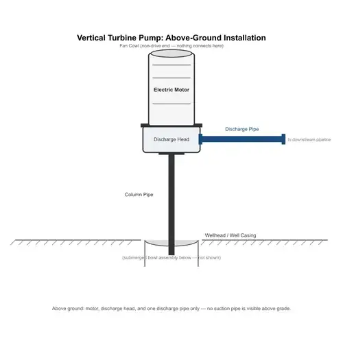
A vertical turbine pump is a surface-motor-driven, multistage centrifugal pump with its impellers and diffuser bowls suspended below the water level in a well, sump, or intake structure. Selection comes down to four things: the correct setting depth, the right bowl assembly stage count and material, the line shaft lubrication method, and a workable NPSH margin. Get any one of those wrong and you can end up with cavitation, vibration, premature bearing wear, or an expensive pump to pull and service.
That last point matters more than most buyers expect. A vertical turbine pump is not a commodity you can swap in an afternoon. Pulling a deep-set vertical turbine pump for a bowl or shaft repair usually means crane time, wellhead isolation, column disassembly, and days of downtime. In municipal water supply, cooling water intake, or irrigation duty, that cost can often exceed the difference between a properly specified pump and a cheap provisional selection. The real purchasing decision is therefore about reliability under site conditions, not just duty-point pressure.
This guide walks through the components you must specify, how to calculate setting depth from water-level data, how to verify NPSH margin, how to choose bowl stages and materials, and what to demand during factory testing. Use it to prepare an RFQ that forces a supplier to show engineering judgment instead of sending back a generic quote.
Quick Answer / 30-Second Buyer Decision
For most municipal, irrigation, cooling water, and intake applications, the selection path looks like this:
- Base the setting depth on the dynamic pumping water level, never on the static water level.
- Keep the suction bell low enough to satisfy minimum submergence and prevent vortexing.
- Select bowl stages from the required total head at the actual duty flow, not from a loose “future capacity” assumption.
- Match bowl and impeller materials to the fluid—potable, brackish, sandy, or corrosive—not just to the pump application.
- Choose open water-lubricated line shafts for clean potable service and low-sand wells; choose enclosed tube shafts where sand or deeper settings demand protected bearings.
- Confirm the first-stage impeller NPSH requirement and verify available suction pressure from the submerged bowl position.
If you only have time to check one thing before issuing a purchase order, check whether the supplier calculated the suction bell depth from the lowest dynamic water level at maximum flow, not from a static measurement. That single mistake is one of the most common causes of vortexing, air entrainment, and cavitation failures in vertical turbine pump installations.
In other words: a vertical turbine pump is simple in concept but unforgiving in application. The rest of this page gives you the concrete specification and supplier-verification detail.
Scope of This Guide
This article covers the engineering and sourcing decisions for vertical turbine pumps used predominantly in:
- Municipal well fields and booster supply
- Irrigation districts and canal intake pumping
- Cooling water circulation and intake structures
- Industrial process water intake and raw water transfer
- Wet pit and sump installations where the motor stays above the liquid
The focus is on vertical turbine pumps with an above-ground motor and a long line shaft coupled to a submerged bowl assembly. It does not cover fully submersible borehole pumps, residential shallow-well systems, or general end-suction centrifugal pump design. If your application is a short-set industrial drainage or sump application rather than a deep well, vertical sump pumps are a related but different selection path.
The thread through every section is the same: the supplier can only size the pump correctly if the buyer supplies real site data. A well-written RFQ often solves more problems than any after-the-fact price negotiation.
Anatomy of a Vertical Turbine Pump: Core Components
A vertical turbine pump is modular. Buyers who treat it as one item usually under-specify something critical. Break the assembly into three sections and specify each one separately.
At the top is the discharge head assembly. This is the above-ground foundation that supports the motor, carries the thrust load, and seals the line shaft where it exits the discharge head. It can be designed for vertical hollow-shaft motors with an adjustable coupling nut, or for solid-shaft motors with a rigid coupling. The discharge nozzle can be flanged or threaded. Buyers should specify the discharge head surface: painted cast iron, stainless steel, or another wetted coating depending on the environment above the well.
Next is the column assembly. This is the long vertical pipe that conducts water upward while the line shaft rotates inside it. Column pipe sections can be flanged or threaded; flanged joints are heavier but easier to disassemble for maintenance. Inside the column, the line shaft runs through bearing spiders or bearing retainers spaced along its length. Shaft couplings and straightness matter here. A long column assembly is also a structural and vibration problem, not just a pipe run. Shaft critical speed, coupling alignment, and bearing spacing must match the total setting depth.
At the bottom is the bowl assembly. This is the hydraulic heart of the pump. The bowl assembly includes the suction bell, one or more impellers, diffuser bowls, bowl bearings, and wear rings. In a clean-water vertical turbine pump, each impeller and diffuser pair forms one stage. The suction bell is the intake at the bottom; its design and submergence control vortex formation. In wet-pit or short-set configurations, the bowl assembly may be directly below the discharge head instead of hundreds of meters down a well.
Between the motor and the bowl assembly, the line shaft is the component most buyers forget to specify. It transmits torque and supports thrust from the impeller stages. Shaft diameter, coupling style, and bearing lubrication are not afterthoughts. They help determine whether the pump can run reliably for years or fail early on sand or misalignment.
This modular structure is why vertical turbine pump applications range so widely. A municipal well can use a stainless steel bowl assembly with an open line shaft; a cooling water intake may use a short-set vertical turbine with a mixed-flow first stage; an irrigation district can run a large borehole pump with bronze impellers and an enclosed oil-lubricated shaft. The same core architecture adapts, but each section must be specified for the actual site.
Where Vertical Turbine Pumps Fit and Where They Do Not
For B2B buyers, the fastest way to avoid the wrong technology is to match the pump type to the physical access and motor location.
Vertical turbine pumps make sense when:
- The motor must remain above ground for electrical safety, accessibility, or atmosphere constraints
- The water source is a deep well, a deep intake structure, or a wet pit where a horizontal pump would need long suction piping
- Large flows at medium to high head are required, and multiple stages can be stacked economically
- The application benefits from a submerged first stage, which reduces suction lift and cavitation risk
- Maintenance crews prefer to service the motor and shaft seal without pulling a submersible motor
Vertical turbine pumps fit poorly when:
- The entire water source is shallow and horizontal suction is straightforward
- The liquid contains high solids or fibrous material that will clog bowl diffusers
- The installation has no vertical clear height for pulling the column in sections
- The project calls for a small residential water supply where a simple submersible pump is cheaper and simpler
- The motor must be underwater, which describes a submersible pump, not a vertical turbine
The distinction matters because some distributor catalogs blur the two. A vertical turbine pump has a dry motor at the surface and a long shaft to the bowls. A submersible pump has a hermetically sealed motor directly coupled to the bowls underwater. The maintenance, cable, sealing, and thrust logic are completely different.
How Setting Depth and Water Level Dictate Pump Configuration
Setting depth is the distance from the discharge head mounting surface to the suction bell inlet. If you send an RFQ that says “100-meter well” without water-level data, a good supplier will immediately ask for more. A less careful supplier will quote a pump that matches the well depth instead of the hydraulic duty.
Start with three water levels:
- Static water level is the undisturbed water surface before pumping starts.
- Drawdown is the drop from static level caused by pumping at a given flow rate.
- Dynamic water level is the actual water surface while pumping at design flow.
Setting depth must place the suction bell below the lowest expected dynamic water level by at least the required minimum submergence. Minimum submergence is not a guess. It depends on suction bell velocity, bell diameter, flow rate, and intake geometry. Too little submergence creates a vortex that pulls air into the first-stage impeller, causing vibration, reduced flow, and surface pitting. Too much extra setting depth adds column sections, shaft length, bearing count, and cost without adding hydraulic value.
For a deep well, the casing inside diameter also limits the bowl diameter and flow capacity. The pump must fit with enough clearance for installation and inlet flow. The installer needs to know the casing I.D., any casing reductions, and whether the well is straight enough for a long column.
For a wet pit or cooling tower sump, the setting depth is shorter, but the same principle applies. The suction bell still needs submergence relative to the lowest operating water level in the sump. Intake width, velocity, and separation from walls also affect vortex risk. If the sump is too small or narrow, extra submergence often cannot fully correct a poor intake flow pattern.
Practical rule: if you only know the static level, the pump may be set too shallow. Installers often record static level because it is easy. The engineering selection must use the drawdown number from a pumping test or aquifer study. Where no pumping test exists, treat the drawdown as unconfirmed and require the supplier to state their assumption. For borehole-specific water supply decisions, the deep well pump selection guide goes deeper into yield, casing clearance, and power supply for drilled wells.
NPSH and Cavitation Prevention in Vertical Turbine Pumps
NPSH confuses many buyers because they associate it with suction lift on horizontal pumps. A vertical turbine pump is different—the first-stage impeller is already submerged. That submerged position provides positive suction head. The question is whether the available suction pressure is enough above the pump’s required NPSH.
The buyer only controls the system side:
- Atmospheric pressure at the site
- Liquid vapor pressure, which depends on temperature and fluid composition
- Water column height from the suction bell to the first-stage impeller
- Liquid level above the impeller eye
- Intake and suction bell losses
The pump supplier controls the required side:
- First-stage impeller suction geometry
- Inlet passage design
- Rotational speed and flow range
- Whether a low-NPSH first stage or larger suction bell is needed
NPSH margin is the difference between NPSHa available from the system and NPSHr required by the pump. A safe selection should not accept NPSHa equal to NPSHr at the duty flow. Margins vary by standard and energy level, but a thin margin at maximum flow or low dynamic level is often where vertical turbine pumps fail silently. Cavitation may not sound dramatic in a submerged bowl. The symptoms show up later as impeller pitting, lower head, or vibration.
Buyers should demand the first-stage bowl curve and NPSHr curve at the quoted speed. Then compare those values with the lowest dynamic water level, not the average. If the supplier cannot provide an NPSHr curve for the proposed first stage, do not accept the quote as engineering-proven.
The first-stage impeller is the most important part of NPSH control. In some vertical turbine applications, the pump uses a specially designed first-stage impeller with a larger eye or a different vane geometry to reduce NPSHr. This is a legitimate engineering trade-off, but it affects first-stage performance. Do not let a supplier add a low-NPSH first stage without explaining the performance impact.
Bowl Assembly Design: Calculating Stages and Selecting Materials
The bowl assembly is where head is generated. Each impeller and diffuser bowl adds pressure incrementally, stage by stage. That is why vertical turbine pumps are sometimes described as bowl assembly pumps: the hydraulic duty is built by stacking bowls, not by changing a single impeller.
Stage count starts with total dynamic head at the required flow. The supplier selects a bowl size, then divides the required head by the practical head per stage. However, stage count is rarely a simple arithmetic answer. Larger bowls can produce more flow but may have different per-stage head. Smaller bowls fit narrow well casings but may need more stages or higher speed. Each added stage increases shaft length, column weight, thrust load, and bearing count. More stages can also push the rotor closer to a critical speed limit over long column settings.
Do not specify extra stages “for future head.” That adds cost, shaft stress, and potential vibration without improving current reliability. If future demand is real, specify the current duty point and the future duty point separately. The supplier can verify whether a single pump can cover both, or whether a different bowl or speed makes more sense.
Multistage pump selection uses the same hydraulic principle—stacked impellers in series—but the vertical line shaft, motor support, and submergence logic are specific to vertical turbine pumps.
Material selection follows the fluid more than the pump type. Clean potable water often suits cast iron or bronze components, but potable service adds compliance requirements. Brackish or seawater pushes you toward stainless steel or duplex to resist chloride pitting. Sandy water requires wear-resistant coatings or hard alloys, and that choice must be paired with the correct line shaft protection.
Table: Bowl Assembly Material Selection Matrix
| Fluid Type | Recommended Bowl Material | Recommended Impeller Material | Notes |
|---|---|---|---|
| Clean water / municipal potable | Cast iron or fabricated steel with approved coatings | Bronze or stainless steel | Confirm NSF/ANSI 61 wetted materials where required |
| Brackish / seawater | 316 stainless steel or duplex stainless steel | 316 stainless steel or duplex | Higher chloride resistance; confirm alloy grade for actual salinity |
| Sandy / abrasive water | Cast iron or steel with wear-resistant coatings or liners | High-chrome or abrasive-resistant alloy | Combine with enclosed line shaft and hard wear rings |
| Corrosive industrial | 316 stainless steel, duplex, or alloy suited to fluid chemistry | Matching compatible alloy | Require material certificates and chemical compatibility review |
Line Shaft Configuration: Open vs. Enclosed Lubrication
The line shaft is a long rotating column. It needs bearings and lubrication along its entire length. The two standard approaches are open shaft and enclosed tube shaft.
Open shaft, water-lubricated designs use the pumped water as the bearing lubricant and coolant. Bearing materials are typically rubber, elastomer, or other water-resistant materials running on a hardened shaft sleeve. Open shafts are simple, have fewer sealing components, and introduce no oil into the water path. They are common in potable water service because there is no oil contamination risk. The weakness is sand. In sandy water, abrasive particles passing through the line shaft bearings wear the rubber and the shaft sleeve quickly. Open shafts also tolerate dry running poorly; they should have water in the column before start-up.
Enclosed tube, oil-lubricated designs run the line shaft inside a protective tube. A clean oil supply lubricates the bearings and keeps abrasive particles away from the shaft. This style is better for agricultural wells with sand, river intakes, or deeper settings where bearing reliability matters. The trade-off is contamination risk: an oil leak can reach the pumped water. Some enclosed designs use clean water fed from outside instead of oil. Neither approach is automatically better. The choice depends on fluid quality, environmental limits, potable regulations, and the owner’s ability to maintain the oil system.
Table: Line shaft comparison.
| Feature | Open Shaft, Water Lubricated | Enclosed Tube, Oil or Clean Water Lubricated |
|---|---|---|
| Lubricant source | Pumped water | External oil reservoir or clean water feed |
| Potable water risk | Low; no oil in contact | Oil leakage risk if oil-lubricated |
| Sand tolerance | Low; bearings wear quickly in abrasive water | Better; bearings protected inside tube |
| Dry-run tolerance | Poor | Better but still not indefinite |
| Maintenance | Simpler, fewer parts | More parts: oil reservoir, tube, leak checks |
| Typical use | Municipal drinking water, low-sand clear water | Sandy irrigation wells, industrial intakes, deeper settings |
If the application is potable water and the buyer insists on an enclosed shaft, the supplier must confirm that the enclosed system uses a non-contaminating design or a clean water flush rated for drinking water. Do not assume every enclosed shaft is compatible with potable service.
Vertical Turbine Pump Maintenance Factors That Decide Lifecycle Cost
Maintenance starts at specification, not after installation. A vertical turbine pump that is hard to pull or expensive to service usually has a specification problem, not just a wear problem.
The highest-cost maintenance event is pulling the pump from the well or intake. Every extra column section adds pulling time. For deep settings, the buyer should confirm:
- Flanged versus threaded column joints and how they affect disassembly speed
- Whether the setting depth allows pulling in manageable column sections
- How the site will access the wellhead with a crane or hoist
- Whether the discharge head design permits shaft and bearing inspection without disturbing the bowl assembly
Bowl wear, impeller clearance, and wear ring condition are the next major maintenance variables. Replaceable wear rings are common on municipal and industrial clean-water pumps, but not every supplier includes them. For sandy water, hardened wear rings and replaceable bowl bearings should be specified at the RFQ stage. Do not wait until the first premature bowl failure.
Seal design also affects maintenance. The discharge head shaft seal may be a mechanical seal or a packing gland. Packing requires periodic adjustment and a controlled leakage rate. A mechanical seal reduces leakage but is more sensitive to shaft runout and abrasive particles. The owner’s maintenance capability should drive the choice. A pump station with no daily operator may do better with a mechanical seal, while a plant with an operator and simple water service may accept packing.
Dry-run protection and pre-lubrication are critical for new installations. Open line shaft bearings can be damaged if the motor starts before the column is filled with water. Start-up controls, pump-down level switches, and low-level cutouts protect both the motor and the submerged bowl assembly. If the pump manufacturer does not ask about your control scheme, the application data is incomplete.
Factory Testing and Industry Standards (ANSI/HI, API 610)
A reliable vertical turbine pump supplier should be able to show performance test results, not just a catalog curve. Factory tests confirm that the assembled pump meets the quoted head, flow, efficiency, and NPSH behavior within an agreed tolerance.
The standards buyers should recognize:
- ISO 9906:2012 defines hydraulic performance acceptance tests and test grades for rotodynamic pumps. Buyers should specify the acceptance grade in the RFQ and ask what tolerance band applies to the duty point.
- ANSI/HI 2.3-2013 covers vertical pump design and application for vertical turbine, mixed flow, and axial flow pumps. It is the reference many North American municipal and industrial buyers expect.
- ANSI/HI 9.6.1 addresses NPSH margin and suction performance. Use it when comparing NPSH margins and first-stage suction requirements.
- API 610 / ISO 13709 applies to vertical pumps in refinery, petrochemical, and gas processing service. It brings added requirements for materials, bearing life, vibration, and documentation.
Hydrostatic testing of the bowl assembly and column confirms pressure integrity. Rotor dynamic balance checks help with vibration in high-speed or deep-set machines. Witnessed or non-witnessed tests should be stated in the RFQ because they affect both cost and delivery time.
Request the following from the factory before accepting a quote:
- Certified performance curve with the guaranteed duty point marked
- The specific test standard and acceptance grade, not just “tested”
- Hydrostatic test report or procedure for the column and bowls
- NPSHr curve for the first-stage bowl configuration
- Material certificates for wetted parts
- Rotor balance report for long line shaft assemblies
- Installation, operation, and maintenance manual availability
A supplier that quotes only “standard factory test” without a standard reference is not giving you enough to hold them accountable. Ask for the standard number.
Supplier Verification Before You Send an RFQ
Beyond the factory test, the buyer should check whether the supplier actually understands vertical turbine pump specification. One of the fastest tests is the supplier’s first round of questions. A capable vertical turbine supplier usually asks about dynamic water level, casing I.D., sand content, line shaft preference, available voltage, and motor thrust load. A weak supplier asks only for flow and head.
Other verification points:
- Ask whether the supplier selects the first-stage bowl based on the lowest dynamic water level or only on the static water level.
- Request a sample line shaft critical speed calculation or a statement of the rotor’s maximum allowable setting depth for the proposed shaft diameter and couplings.
- Confirm that the bowl assembly material and wear ring replacement philosophy match the fluid analysis.
- Ask about bearing spacing along the column and whether the supplier includes bearing retainers for long settings.
- Clarify who sizes the motor thrust bearing and whether the motor supplier receives the complete thrust load calculation.
- For potable water, request acceptable wetted-material compliance documentation and the applicable standard in the target market.
Do not expect a supplier to volunteer all of this. You are the buyer, and the RFQ is your best tool to force disciplined engineering.
Vertical Turbine Pump RFQ Checklist
Use this table as your technical data sheet. Send it with every vertical turbine pump inquiry. Fill in every field you can; write “TBD” or “need supplier recommendation” for the rest.
| Field | Your input or options |
|---|---|
| Design flow rate | m³/h or GPM |
| Total dynamic head at duty flow | m or ft |
| Static water level | m below grade or reference point |
| Dynamic/pumping water level at design flow | m below grade |
| Pumping test or aquifer drawdown data | Available / not available |
| Well casing I.D. or sump dimensions | mm or inches |
| Minimum submergence available or required | m |
| Liquid type | Potable, raw river, brackish, seawater, wastewater, other |
| Solids concentration | mg/L or % by mass |
| Maximum particle size | mm or grit size |
| Liquid temperature | °C or °F |
| Specific gravity | Numeric value |
| Bowl and impeller material preference | Cast iron, 304 SS, 316 SS, duplex, bronze, high-chrome, other |
| Line shaft type | Open water-lubricated / enclosed tube / supplier recommendation |
| Desired discharge head seal | Packing / mechanical seal / supplier recommendation |
| Motor power, voltage, phase, frequency | kW/HP, V, phase, Hz |
| Motor enclosure and thrust bearing | TEFC, WPI, vertical hollow shaft, solid shaft, thrust rating |
| Required standards and tests | ISO 9906 grade, ANSI/HI, API 610, hydrostatic test, witness point |
| Documentation required | Curves, material certs, balance report, O&M manual, spare parts list |
| Packaging and transport | Sea freight crate, export marking, long column section handling |
This checklist also helps you compare quotes. If two suppliers quote different bowl materials or stage counts because they made different assumptions, the RFQ shows exactly where their assumptions diverge. That is a buying signal, not a nuisance.
Common Specification Mistakes
The same mistakes appear repeatedly in vertical turbine pump procurement. Avoid them deliberately.
- Using static water level instead of dynamic level. This places the suction bell too shallow once drawdown occurs, causing vortexing and air ingestion.
- Ignoring minimum submergence. More depth than the dynamic level is required. The suction bell must sit meaningfully below the lowest pumping level.
- Specifying extra stages for future flow without a future duty point. It adds cost, shaft stress, and complexity without a confirmed benefit.
- Selecting open line shafts for sandy service. Sand erodes open shaft bearings quickly, even when the bowl materials are hardened.
- Selecting oil-lubricated enclosed shafts for potable wells without confirming non-contamination design. The oil leak risk may violate drinking water requirements.
- Omitting the well casing I.D. from the RFQ. The supplier cannot confirm that the bowl assembly fits the bore or that there is enough clearance for flow and installation.
- Not specifying test standards and tolerance grades. A generic “tested” statement gives the buyer no enforceable performance claim.
- Forgetting motor thrust load. A vertical hollow-shaft motor must handle the full hydraulic downthrust plus rotor weight. Undersizing the thrust bearing fails early and expensively.
- Ignoring pulling access. A pump specified without clear column section lengths and rigging access can be impossible to service without major civil work.
FAQ
These answers cover the most common long-tail questions a B2B buyer asks before contacting a vertical turbine pump supplier.
How deep can a vertical turbine pump go?
There is no universal maximum depth. The practical limit for a given pump is set by line shaft critical speed, shaft tensile strength, thrust bearing capacity, column pipe pressure rating, and the available casing diameter. Many municipal and irrigation installations run at depths that depend on these mechanical limits, while deeper settings are possible with special shaft materials, larger couplings, and more bearing spacers. Any deep well turbine pump selection must include a line shaft deflection or critical speed check from the manufacturer, not just a bowl performance curve.
What is the difference between a vertical turbine pump and a submersible pump?
A vertical turbine pump keeps the motor above ground and drives the submerged bowl assembly through a long line shaft. The motor is dry, accessible, and can be larger or easier to ventilate. A submersible pump places a sealed motor directly below the bowls in the water, which shortens the drive train but introduces cable, seal, and motor-cooling requirements. From a maintenance standpoint, submersible pumps are pulled complete, while vertical turbine pumps are disassembled column section by section. If you are deciding between the two for a deep well, submersible vs surface pumps explains the trade-off in more detail.
How do you calculate the number of stages for a bowl assembly?
The supplier typically selects a bowl size and speed first. Then they divide the total dynamic head at the duty flow by the practical head produced by one bowl stage at that flow. The result is the initial stage count, which is then checked against rotor dynamics, thrust load, column weight, and shaft length. As a buyer, you should ask for the stage curve or per-stage head at the duty point and verify that the offered pump meets the required total head without excessive extra stages. Stage selection is a hydraulic and mechanical calculation, not a simple division done in isolation.
How often does a vertical turbine pump need maintenance?
Maintenance frequency depends on water quality, setting depth, bearing form, and pump materials. Clean water with a properly specified pump may run for long intervals between inspections, while sandy or chemically aggressive service can demand shorter inspection intervals. The most expensive maintenance event is usually pulling the pump. Buyers should specify wear-resistant materials and line shaft protection based on fluid analysis to extend the interval. The supplier’s O&M manual should state pre-lubrication, vibration, and bearing inspection requirements.
Can a vertical turbine pump handle sand or solids?
Vertical turbine pumps are not solids-handling pumps. Small amounts of fine sand can be tolerated with hard wear rings and protected line shaft bearings, but heavy sand or coarse particles accelerate wear in bowl diffusers, impellers, and line shaft bearings. For abrasive service, the buyer must specify abrasive-resistant materials and sand concentration data. For lighter solids or wider clearances, a different pump design may be more appropriate.
Official Sources and Compliance References
Use these standards to make your RFQ concrete and enforceable.
- ANSI/HI 2.3-2013 supports vertical turbine pump design, application, and general requirements for vertical pumps.
- ANSI/HI 9.6.1 supports NPSH margin evaluation and suction performance.
- ISO 9906:2012 supports hydraulic performance acceptance tests and tolerance grades.
- API 610 / ISO 13709 supports vertical pump requirements for refinery, petrochemical, and gas processing service.
- NSF/ANSI 61 supports wetted material compliance for drinking water components in many regulatory markets.
Do not treat standards as a commodity checkbox. A quote that says “API 610” should also state the edition, the pump service class, and the specific documentation package. A quote that says “ISO 9906” should state the acceptance grade, such as 1B or 2B, and the duty-point tolerance. Without those details, the standard name is only marketing.
Conclusion
A vertical turbine pump is a straightforward concept built from a precise set of modular decisions. The buyer who understands setting depth, bowl stage logic, NPSH margin, and line shaft lubrication is far more likely to get a pump that fits the well or sump and keeps running without surprise failures. The buyer who only sends flow and head may get a quote, but not necessarily a reliable machine.
Put the engineering pressure on the supplier early. Send measured dynamic water levels, ask for the first-stage NPSHr curve, specify the test standard and grade, and make the supplier state how they calculated stage count and setting depth. That is the difference between a vertical turbine pump that lasts and one that becomes a scheduled maintenance problem.
Get A Quote

Get A Quote
0 Comments