
Vertical Inline Pump Guide: Working Principle, Applications, and Selection Criteria
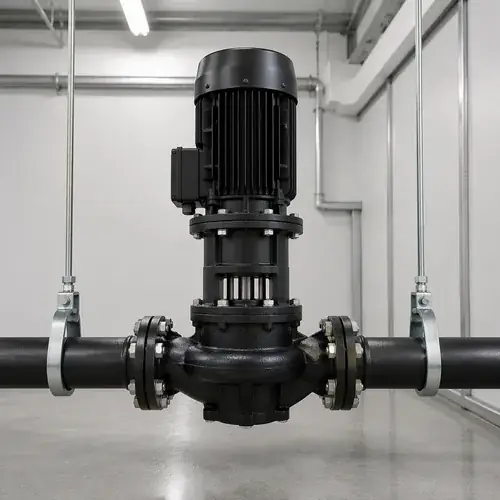
If you're reading this, there's a fairly good chance you need to move clean water or glycol through a building, an industrial process, or a cooling loop — and floor space is tight. That's exactly the scenario where a vertical inline pump earns its keep. In short, it's a single-stage centrifugal pump where the suction and discharge ports sit on the same horizontal centerline, the motor mounts vertically above the casing, and the whole assembly slips directly into the pipe run. No baseplate. No alignment hassle. No sprawling footprint.
But the decision is never just about space. The real question procurement engineers and HVAC contractors ask is: will the inline configuration hold up mechanically, can I maintain it without tearing half the pump room apart, and will it actually deliver the flow and head the system curve demands — including when loads shift? This guide answers all of that. We'll walk through the operating principle, map out where vertical inline pumps make commercial sense, and then draw a practical line between this design and a frame‑mounted centrifugal pump — because that distinction is what stops many buyers from ordering the wrong machine.
By the end, you'll have a selection framework you can hand to a supplier, an RFQ checklist you can use tomorrow, and enough mechanical context to push back when a quote recommends a configuration that doesn't match your duty. No generic marketing. Just the engineering and procurement logic that comes from watching these pumps succeed — and fail — in real installations.
Quick Answer: When You Should Choose a Vertical Inline Pump
Pick a vertical inline pump when: - You're handling clean or mildly treated water‑based liquids (HVAC loops, chilled water, hot water, booster systems, closed‑loop cooling). - The total dynamic head stays within the single‑stage centrifugal envelope — typically around 50 to 160 meters of head, depending on the model. - You need to reduce floor footprint dramatically, and your pipework can absorb the pump weight without putting dangerous loads on the casing. - Maintenance access above the pump is acceptable — you'll need clearance to lift the entire motor‑and‑impeller assembly straight up. - You're comfortable with the bearing and seal life trade‑off that comes with a close‑coupled design versus a separately coupled frame‑mounted pump.
Skip a vertical inline pump — and specify a frame‑mounted centrifugal instead — when: - The liquid contains even modest solids, abrasives, or stringy material that will wrap around an impeller or destroy a mechanical seal. - Flow rates and pipe sizes climb well above 8 inches (200 mm), where the weight of the pump body hanging in the pipe run becomes a structural problem. - You need heavy‑duty bearing support for continuous 24/7 operation over decades, and you can afford the extra footprint and foundation work. - The pump room layout forces you to service the pump from the side rather than from above.
If you're on the fence, the section Vertical Inline Pump vs Frame‑Mounted Pump will walk you through the specific mechanical criteria that tip the decision one way or the other.
Scope of This Guide
This guide covers single‑stage, close‑coupled vertical inline centrifugal pumps used primarily in HVAC, commercial building services, industrial cooling, and clean‑water booster applications. We'll look at: - Mechanical arrangement and the implications for installation, vibration, and maintenance. - Application fit — where inline pumps thrive, and where they turn into a constant source of downtime. - A practical head‑to‑head comparison with frame‑mounted centrifugal pumps, including a decision table you can use during project meetings. - Selection logic covering flow, TDH, NPSH margin, motor sizing, VFD operation, and material compatibility for typical HVAC and industrial water. - Installation and commissioning best practices that directly affect reliability and warranty. - A detailed RFQ checklist so your supplier receives a technically tight inquiry, not a vague “send me your best price.”
We're not going to dig deep into positive displacement pumps, slurry handling, open‑channel sewage, or fire pump certification requirements — those deserve their own dedicated discussions.
What Is a Vertical Inline Pump?
A vertical inline pump is a centrifugal pump designed to be installed directly in a pipe run, with the suction and discharge flanges sharing the same centerline. The motor sits vertically on top of the pump casing, and the impeller mounts directly on the motor shaft extension — that's the “close‑coupled” part. Port‑to‑port, the pump takes up no more length than a well‑placed pipe joint.
That same‑centerline arrangement matters more than most buyers realize. It eliminates the suction and discharge elbows you'd normally need with an end‑suction pump, which reduces pipe‑fabrication cost and frees up floor space. Instead of bolting a pump base to a concrete pad and aligning a separate motor, you pick the pump up, drop it between two flanges, and bolt it in place. The pipe hangers carry the weight — not a foundation.
The vertical orientation, however, introduces considerations you don't face with a horizontal end‑suction machine: the shaft seal sits directly below the motor, so any seal leak can drip onto the motor (or into the drain, depending on the design), and lifting the motor‑and‑impeller assembly for a seal replacement requires overhead clearance. But for hundreds of thousands of HVAC installations worldwide, these trade‑offs land firmly on the “worth it” side of the ledger because of the space and piping savings.
How Does a Vertical Inline Pump Work?
Centrifugal Operating Principle
Like any conventional centrifugal pump, a vertical inline pump relies on rotational energy transfer. The motor spins the impeller at a fixed speed (or variable speed if you're using a VFD), and the impeller vanes accelerate the liquid radially outward. As the liquid leaves the impeller at higher velocity, the volute casing converts that velocity into pressure — the standard dynamic‑to‑static pressure conversion you see in every centrifugal pump curve.
The key difference isn't in how pressure is generated — it's in the mechanical arrangement of the rotating assembly and the flow path, which we'll look at next.
Main Components and Flow Path
From the bottom up, you've got a suction flange, an impeller inside a concentric or volute casing, a discharge flange on the opposite side, a mechanical seal on the shaft, and an electric motor mounted vertically with the shaft pointing down into the pump. Liquid enters through the suction flange, flows into the impeller eye, gets thrown outward, collects in the volute, and leaves through the discharge flange. Because suction and discharge sit on the same horizontal axis, the pump doesn't redirect the pipe run — it just occupies a single point in the line.
What really matters to the maintenance team: the mechanical seal is the primary wear component here. Seal material selection — carbon, ceramic, silicon carbide versus tungsten carbide faces, with EPDM or Viton elastomers — directly sets the boundaries for water temperature and glycol concentration. A wrong elastomer choice, and you may be pulling the motor up to replace a swollen or cracked secondary seal within months.
Close‑Coupled and Back Pull‑Out Designs
Most vertical inline pumps use a close‑coupled architecture: the impeller fastens directly to the motor shaft, and the motor flange bolts to the pump casing. This eliminates shaft alignment entirely — there's no separate pump shaft and coupling to align. You get a compact machine, but the motor bearings end up absorbing the radial thrust from the impeller. On clean‑water HVAC duty at moderate pressures, this works fine for a long time. On heavy‑duty applications — high‑head, continuous variable‑speed operation, or larger impeller diameters — those same motor bearings may see reduced life. That's a design trade‑off you need to accept upfront.
The back pull‑out feature is what saves maintenance labor. You can unbolt the motor‑and‑casing cover assembly and lift the entire rotating element — motor, shaft, impeller, seal — straight up out of the pump housing without disconnecting the suction and discharge piping. That means a seal replacement or impeller inspection doesn't mean draining the entire loop or cutting out the pump. But you must have enough clearance above the pump for a chain block or crane. Many compact pump rooms fail this test, and then the owner discovers the “easy maintenance” feature is useless because a pipe rack sits 300 mm above the motor.
Where Are Vertical Inline Pumps Commonly Used?
Here's a practical mapping of where vertical inline pumps earn their placement — and where they don't:
| Application | Typical Conditions | Inline Suitability | Notes |
|---|---|---|---|
| Chilled water circulation | 4–20°C, clean glycol mixes, moderate head | Excellent | The default choice in most HVAC plant rooms |
| Hot water heating loops | Up to 120°C, treated closed‑loop water | Good (confirm seal temperature rating) | Need high‑temp mechanical seal elastomers and motor bearing grease |
| Commercial booster systems | 3–8 bar discharge, variable flow | Excellent | Works well in multi‑pump VFD setups |
| Cooling tower condenser water | Clean water, possible debris from open towers | Cautious — install strainers | Debris and solids can damage seals quickly |
| Industrial cooling water | Clean process cooling, closed‑loop | Good | Check material compatibility if water quality is poor |
| Fire protection services | Clean, specific pressure/flow must comply with codes | Specialized — not covered here | Fire pump certification adds a layer of complexity beyond standard selection |
| Dirty water, slurries, sewage | Solids, abrasives, stringy materials | Not suitable | Frame‑mounted or submersible sewage pumps are the right call |
HVAC Chilled and Hot Water Circulation
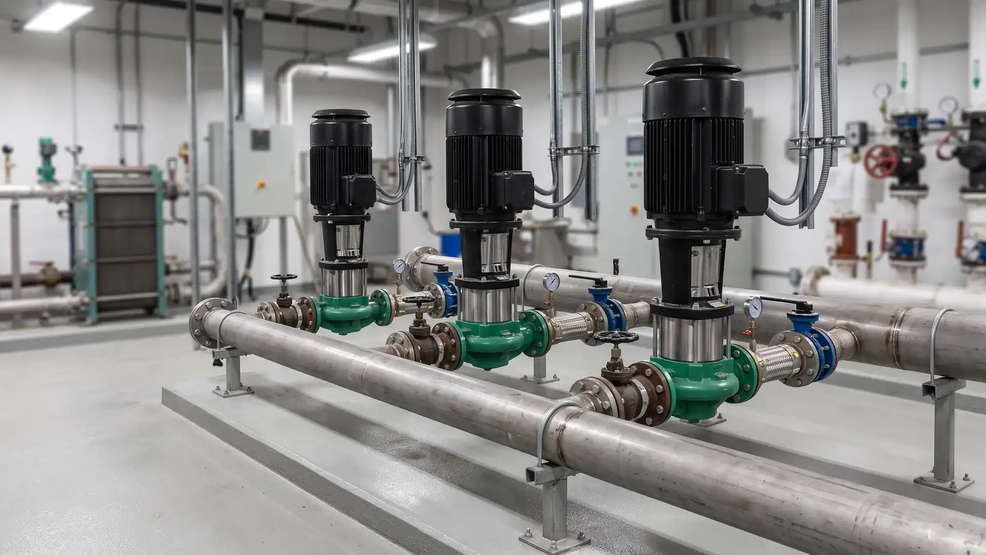
This is the bread‑and‑butter application for vertical inline pumps. Primary‑secondary chilled water loops, condenser water loops, heating hot water loops — all typically demand stable flow at moderate head, with clean water. The inline configuration lets you stack pumps vertically in a mechanical room with minimal footprint, which is exactly what consultants want for high‑rise and large commercial buildings. See our guide on pump systems for commercial buildings for the bigger picture of how inline pumps fit into a full building‑services scheme.
Commercial Building Booster Systems
When you need to maintain constant pressure across a wide range of building loads — think morning demand spikes in office towers — a multi‑pump vertical inline booster skid with VFD control is hard to beat. The pumps share the same pipe manifold, and the vertical arrangement keeps the skid compact. The duty‑standby‑assist logic can be managed through a controller that cycles pumps based on demand. But you have to ensure each pump sees adequate flow even at minimum demand, otherwise you'll dead‑head a pump and cook the seal.
Industrial Cooling and Process Water
Factories and process plants often run closed‑loop cooling water through chillers, heat exchangers, and mold‑cooling circuits. A vertical inline circulation pump fits naturally here if the water stays clean. The moment suspended solids or scale enter the picture, however, you should filter aggressively or switch to a different pump type — not because the inline pump cannot push the water, but because solids settle in the seal area and act like a grinding paste.
Fire Protection and Utility Services
Vertical inline pumps do appear in some fire pump configurations, but the listing and approval requirements are entirely separate from standard commercial pump selection. If you're specifying for fire service, you need to follow a dedicated fire‑pump selection process that accounts for NFPA, FM, or local code testing and certification. This guide stays focused on HVAC, circulation, and clean‑water boosting.
Vertical Inline Pump vs Frame‑Mounted Pump
This is the comparison that separates informed buyers from first‑time specifiers. At the feature level, both pump types move liquid centrifugally. At the system level, they differ in everything that affects long‑term reliability: pipe load handling, bearing life, alignment, and maintenance access.
Space and Installation Differences
| Criterion | Vertical Inline Pump | Frame‑Mounted Pump |
|---|---|---|
| Floor footprint | Minimal — pump occupies same space as pipe run | Large — requires concrete pad and baseplate |
| Piping arrangement | Suction and discharge on same centerline, no elbows needed | End‑suction or top‑suction, needs elbows and pipe supports |
| Foundation work | None — pipe hangers support weight | Reinforced concrete inertia base recommended for vibration control |
| Pump‑to‑motor weight handling | Pipe system absorbs combined pump‑and‑motor weight | Pedestal or baseplate absorbs pump weight; motor sits separately |
| Alignment | Factory‑set via close‑coupled design, no field alignment | Field alignment required between pump shaft and motor shaft |
Maintenance and Bearing Support
The vertical inline pump puts the motor bearings in the direct thrust path. Frame‑mounted pumps use a separate bearing housing with oil‑or‑grease‑lubricated radial and thrust bearings designed explicitly for pump loads. That's a real difference when you're looking at 10‑20‑year life cycle costs. Rebuilding motor bearings on a 55 kW inline pump means pulling the entire assembly, sending the motor to a repair shop, and potentially waiting weeks. On a frame‑mounted pump, you can often replace the pump bearings without touching the motor.
That said, for the majority of HVAC‑sized inline pumps — under, say, 37 kW, running 1,500 rpm on clean water — motor bearing life is typically adequate, and the back pull‑out feature means you can replace the mechanical seal and inspect the impeller with limited downtime. For a deeper dive into the mechanical trade‑offs between close‑coupled and separately coupled designs, read the full breakdown: close coupled vs frame mounted pump.
Vibration and Pipe Load Considerations
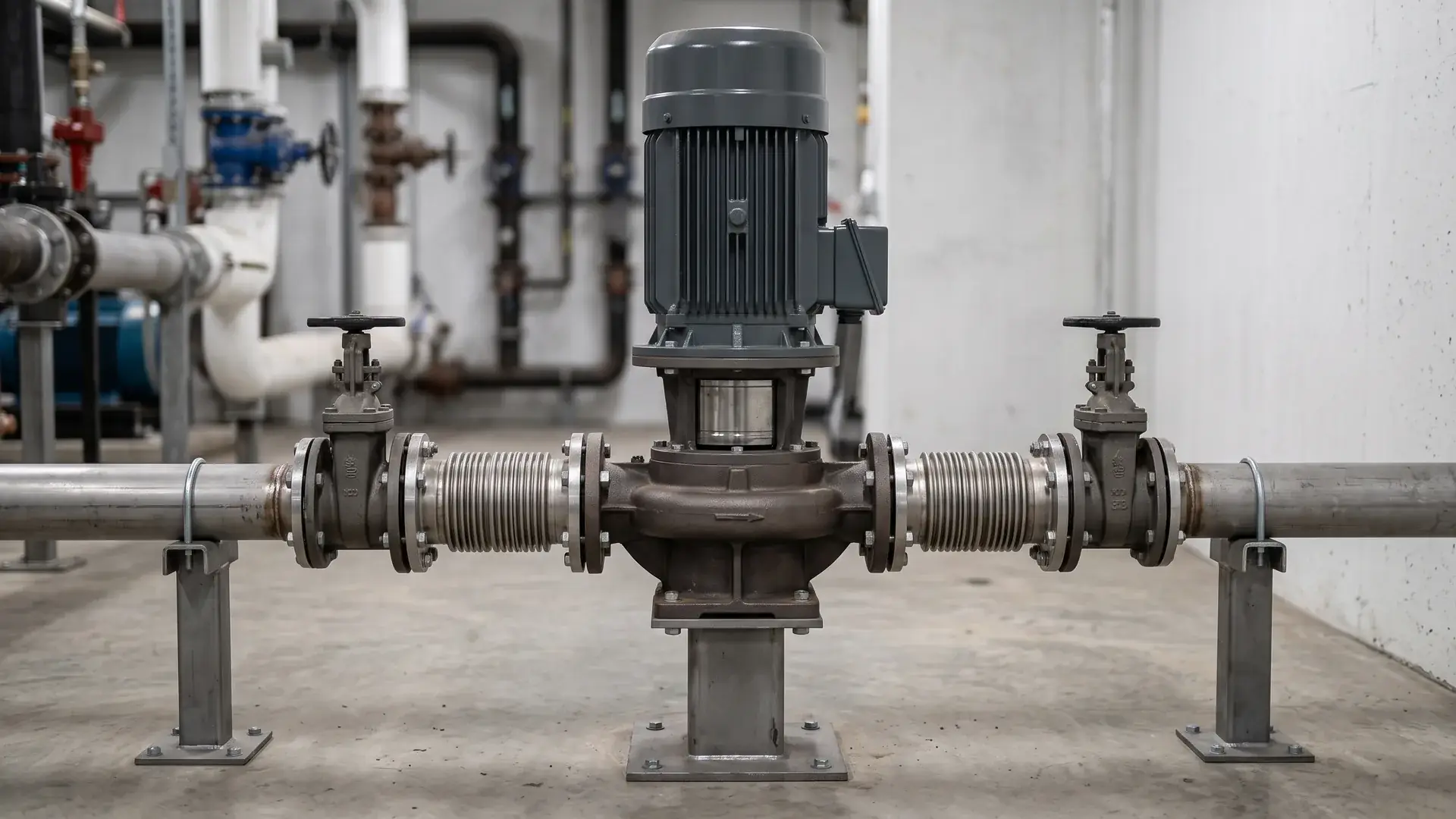
Pipe stress is the silent killer of inline pumps. Because the pump body hangs in the pipe, any misalignment or thermal expansion of the piping gets transmitted directly to the pump casing and, through the close‑coupled flange, into the motor bearings. This is why you see inline pumps installed with flexible connectors and properly anchored pipe supports on both sides — not as a suggestion, but as an operational necessity.
Frame‑mounted pumps are more forgiving in this regard. The pump sits on its own base, and pipe loads are typically isolated from the pump casing by the piping layout and flexible connectors. If you're installing a vertical inline pump in a system with hot water thermal cycling, you need to account for pipe expansion forces explicitly. The supplier's installation manual will state permissible nozzle loads — always ask for those figures.
When a Frame‑Mounted Pump Is the Better Choice
Choose a frame‑mounted pump when: - The flow rate and pipe size exceed 200 mm (8 inches). At these sizes, the weight and thrust loads become a structural concern. - The application runs 24/7 and the cost of downtime is extremely high. The ability to replace pump bearings independently of the motor matters. - Solids or abrasive wear are expected — frame‑mounted pumps often accept wear rings and more robust seal flushing arrangements. - Available headroom above the pump is severely restricted, making overhead lifting impossible. - You need a long‑coupled driver arrangement, such as a diesel engine or a very large motor.
How to Select the Right Vertical Inline Pump
Selection isn't just matching a duty point on a curve — it's matching the pump's mechanical limits to the system's real‑world behavior. The framework below covers the technical inputs you need to send to a supplier, and the checks you should perform before accepting an offered curve.
Flow Rate and Total Dynamic Head
Start with the basics: what flow does your system demand, and what is the total dynamic head required? For closed‑loop HVAC systems, the static head component is typically zero, and TDH is mostly friction loss through pipes, fittings, coils, and chillers. For open‑loop booster or cooling tower circuits, you must add static lift.
The pump's best efficiency point (BEP) should sit squarely on your most frequently expected duty point, not at the design‑day maximum. A pump that operates far left of BEP for most of its operating hours wastes energy, wears bearings faster, and may suffer suction recirculation issues. On the other hand, running far right of BEP risks cavitation and motor overload. Ask for the pump performance curve with the BEP marked and your operating window highlighted — if a supplier can't produce that, walk away. For a broader look at interpreting pump data and completing a full technical selection across different pump types, see our industrial pump selection guide.
NPSH and Cavitation Margin
You need to confirm that the net positive suction head available (NPSHa) in your system exceeds the net positive suction head required (NPSHr) by the pump — with a margin. For clean‑water inline pumps in HVAC, a 20–30% margin is a common starting point, but you should follow the pump manufacturer's recommendation. If your system runs hot water near boiling point or the suction tank is located below the pump, the NPSH margin shrinks quickly. Cavitation will sound like gravel passing through the pump and will destroy the impeller and seal within months.
You calculate NPSHa from atmospheric pressure, liquid height, vapor pressure, and friction losses. You get NPSHr from the pump curve. Never accept a quote that doesn't include NPSHr data.
Motor Sizing and VFD Compatibility
Vertical inline pumps use standard close‑coupled motors — TEFC, IP55, with insulation class appropriate for the fluid temperature. When you add a VFD, motor sizing becomes trickier. Two critical points: 1. The motor must handle the thermal load at low speed, because the motor's cooling fan runs slower and provides less airflow. Many pump manufacturers offer VFD‑rated motors with separate blowers or oversized frames for this reason. 2. The VFD must be programmed with a minimum speed that ensures the pump isn't operated against a closed discharge valve or below the minimum flow required to keep the mechanical seal lubricated. Running dry or near‑dead‑head destroys seals rapidly.
Variable flow systems also push you to check whether the pump can operate with the entire system curve, not just the design point. At reduced speeds, the pump curve shifts, and you need to confirm that the operating point stays within the allowed operating region at every expected speed. If the flow range is wide — common in booster systems — you may need multiple pumps staged with VFD control rather than a single oversized pump.
Material Selection for HVAC and Industrial Water
Most HVAC vertical inline pumps ship with cast iron casings and bronze or cast iron impellers. This combination works for the vast majority of treated closed‑loop systems. For chilled water, a cast iron casing with a bronze impeller and an EPDM‑elastomer mechanical seal is the industry workhorse.
When water chemistry gets aggressive — high chloride content, acidic process water, or high dissolved oxygen at elevated temperatures — you move to stainless steel wetted parts. A pump with a 304 or 316 stainless steel casing, stainless steel impeller, and silicon carbide versus silicon carbide mechanical seal face materials handles much broader water quality ranges, but the price difference is significant. For a real product‑level look at a cast iron inline circulation pump configuration, see this cast iron pipeline circulation pump — it's a typical example of the materials and construction you'd evaluate for medium‑duty commercial service.
Don't guess material compatibility. Give the supplier a water analysis report and ask for a written material recommendation. If the water includes glycol, confirm the elastomer compatibility explicitly.
Noise, Vibration, and Lifecycle Cost
Buyers often overlook two cost drivers: noise and vibration transmitted to the building structure. A vertical inline pump operating near BEP on a properly supported pipe run is relatively quiet. But put a large machine running off‑peak into cavitation, or bolt it to a lightweight steel pipe rack that amplifies vibration, and you'll have complaints from building occupants.
Lifecycle cost analysis should include motor efficiency (IE3 or IE4 depending on regulation), seal life expectancy based on the actual water quality, bearing replacement intervals, and the labor cost of getting to the pump. If your maintenance team needs a scaffold tower to reach a pump hung 4 meters up in a pipe rack, the installation cost savings evaporate fast. Include that labor cost in the TCO spreadsheet.
Installation and Maintenance Best Practices
Even a correctly selected vertical inline pump will shake itself to death if the installation ignores pipe strain and flow disturbances. Here's what to enforce during commissioning.
Pipe Support and Alignment
The pump must not be used as a pipe support. That sounds obvious, but I've seen installations where the "pipe hanger" was essentially the pump casing itself. The piping on both suction and discharge sides needs its own independent supports — rod hangers, structural clamps — so that when you unbolt the flanges, the pipes don't drop and don't pull the pump in any direction. Flexible connectors (braided stainless steel or rubber bellows) on both sides of the pump help isolate vibration, but they must be restrained with tie rods if the system pressure pushes the pipe ends apart. A flexible connector without tie rods installed in a pressurized pipe will expand and pull the pipe, which directly loads the pump flanges — exactly what you're trying to avoid.
Minimum Straight Pipe Requirements
Flow entering the pump impeller should be as uniform as possible. An elbow directly on the suction flange generates uneven velocity profiles that cause impeller hydraulic imbalance and can trigger low‑frequency vibration. A straight pipe section of 5 to 10 pipe diameters upstream of the suction flange is generally recommended, though the exact length depends on the pump type and the upstream fitting. Check the manufacturer's installation manual — and if the manual doesn't mention a minimum straight run, ask the application engineer directly.
VFD Startup and Minimum Flow Protection
During VFD commissioning, confirm the minimum speed setting before the pump ever runs. The minimum speed should correspond to a flow rate that keeps the mechanical seal faces wet and prevents recirculation damage. Some pump controllers include a flow switch or differential pressure sensor that cuts the pump off if the discharge valve closes. Without that protection, a VFD‑controlled pump can inadvertently run against a closed valve at low speed, which generates heat and kills the seal.
Also, set the VFD ramp‑up and ramp‑down times to avoid water hammer. A fast‑closing check valve combined with a sudden pump stop can generate pressure surges that crack valve bodies and pump casings. Ramp the pump down over several seconds, and verify that the check valve closes smoothly.
Seal and Bearing Inspection Intervals
Don't wait for a seal leak to schedule maintenance. A practical baseline for HVAC duty is to schedule inspection every 4,000 to 6,000 running hours or annually, whichever comes first. During inspection, listen for bearing noise with a stethoscope or accelerometer, check for seal leakage at the drain port, and measure vibration at the motor bearing housing. Comparing those readings to the baseline commissioning data tells you whether wear is progressing — long before a catastrophic failure. Keep commissioning vibration data in the maintenance log. Without that reference, you're guessing what "high vibration" means for that specific pump.
RFQ Checklist for Vertical Inline Pumps
Copy this checklist directly into your request for quotation document. Providing incomplete data guarantees incomplete quotes.
| RFQ Field | Your Input / Options |
|---|---|
| Liquid type and concentration | e.g., chilled water, 30% glycol solution, treated boiler feedwater |
| Liquid temperature range | e.g., 5–80°C |
| Required flow rate and unit | e.g., 100 m³/h |
| Required total dynamic head (TDH) | e.g., 35 m |
| System NPSHa at pump suction | e.g., 8 m (calculated at worst-case temperature and level) |
| Power supply | e.g., 415 V / 3 ph / 50 Hz |
| Motor protection class and insulation | e.g., IP55, Class F with Class B rise |
| VFD operation? | Yes / No; if yes, minimum and maximum speed expected |
| Allowable operating range (% of BEP flow) | e.g., 60–110% |
| Pump casing material | e.g., cast iron per ASTM A48 Class 30, or 304 stainless steel |
| Impeller material | e.g., bronze, cast iron, 304 SS |
| Mechanical seal type and face materials | e.g., single unbalanced, carbon versus ceramic; or advise |
| Connection type and standard | e.g., flanged to EN 1092-2 PN16, or ANSI 150 |
| Overhead clearance available for maintenance | e.g., 600 mm above motor top |
| Documentation requirements | Pump performance curve, NPSHr data, motor datasheet, material certs, hydrostatic test certificate, installation manual |
| Inspection requirements | e.g., factory acceptance test to ISO 9906 Grade 2 (confirm) |
| Required spare parts list | e.g., mechanical seal kit, bearing set, casing gasket, wearing ring (if applicable) |
| Quantity needed | e.g., 2 units with duty‑standby configuration |
| Target delivery timing | e.g., required on‑site date or delivery window |
FAQ: Vertical Inline Pump Selection and Operation
Here are the questions I hear most often from engineers and procurement teams who are about to issue a purchase order — or who already have a pump in service and are trying to figure out what went wrong.
Can a vertical inline pump run horizontally?
No. The entire lubrication, seal, and bearing arrangement in a vertical inline pump assumes the shaft is vertical and the motor sits on top. Running the pump on its side would leave the motor bearings inadequately lubricated and could let the mechanical seal run dry or sling lubricant out of position. If you need a horizontal inline pump, you're typically looking at a horizontal end‑suction pump or a separate pump classification. Don't try to modify a vertical mounting — it will fail.
Are inline pumps suitable for dirty water?
Not as a standard choice. Vertical inline pumps are designed for clean or lightly treated water. Solids — even fine silt — can pack into the seal area and accelerate wear, and stringy material can wrap around the impeller. If your water contains solids, you should either install a strainer with sufficient filtration and a pressure drop that your system can tolerate, or choose a pump specifically designed for solids handling, such as a submersible or frame‑mounted sewage pump.
What causes cavitation in HVAC inline pumps?
Cavitation in closed‑loop HVAC systems usually traces back to three causes: (1) system pressure too low at the pump suction due to insufficient static head or a poorly placed expansion tank; (2) a clogged strainer on the suction side, which increases the pressure drop and reduces NPSHa; or (3) operating the pump well beyond its designed flow range, where the NPSHr rises sharply. Open‑loop systems add the risk of low suction tank level and high water temperature. Fixing cavitation requires measuring suction pressure and temperature, comparing NPSHa and NPSHr, and adjusting either the system or the pump operating point.
How much maintenance clearance is needed?
As a baseline, you need enough clearance directly above the pump to remove the motor‑and‑impeller assembly vertically. For a typical 15–30 kW vertical inline pump, that might be 600 mm to 900 mm of clear space above the top of the motor. Your installation must also provide clearance on one side for a crane or chain block rigging, and enough room at the coupling or motor flange area to disconnect cables and bolts. The specific clearance dimension should be confirmed from the pump manufacturer's outline drawing — never assume clearance based on a catalog thumbnail.
Can one inline pump handle variable building loads?
One pump can, provided it's sized correctly and controlled properly. A single vertical inline pump with a VFD can handle a wide load range in, say, a secondary chilled‑water loop with two‑way control valves. But the flow range must stay within the pump's allowed operating region at all speeds. If the building experiences very low nighttime loads that drop flow below the pump's minimum continuous flow requirement, you'll need either a bypass loop, a small pony pump, or a multi‑pump staging strategy. A single pump asked to cover a 10:1 flow range will likely spend too much time at damaging low‑flow conditions.
Conclusion
A vertical inline pump is one of those designs that looks obvious in a catalog but demands real engineering judgment in practice. The space savings are genuine, the installation simplicity is real — but only when the liquid is clean, the pipe loads are properly managed, the NPSH margin is verified, and the maintenance access is physically achievable. Skip any one of those checks and you trade upfront convenience for repeated maintenance calls.
If you're preparing a quotation or a tender specification, start with the duty conditions, then confirm the mechanical limits: seal materials, bearing life expectations, nozzle loads, and overhead clearance. Ask the supplier for documented performance curves and at least basic factory test records — not just a brochure. And if the application pushes the boundaries of what a close‑coupled inline design can handle, run the comparison against a frame‑mounted pump honestly. The right decision saves far more money over ten years than the difference in initial purchase price.
Use the RFQ checklist in this guide to build your inquiry, and insist on clear, technical responses. A supplier that can discuss NPSHr, material compatibility, and VFD minimum speed with you is a supplier worth talking to.
Get A Quote

Get A Quote
0 Comments