
Off-Grid Solar Submersible Pump Sizing Guide: Flow, Head, Panels & Cables
Solar submersible pump sizing starts with two numbers many buyers get backward: the flow rate the pump must deliver during a 4 to 6-hour peak sun window, and the Total Dynamic Head (TDH) the pump must work against when the well is drawn down. Once you have those two points, you match a pump curve, size the solar array with a practical margin, and select a cable that survives the full down-and-back length of the borehole without burning voltage. This guide walks through that calculation in order, because the order matters: you cannot size panels before you know the hydraulic point, and you can't size cable before you know the motor current and voltage.
The commercial risk here is not theoretical. Ignore seasonal drawdown and the motor runs dry. Undersize the array and the pump starts, then dies under load or never reaches the flow the crop actually needs. Pick a thin cable on a deep borehole and you lose enough voltage that the pump runs hot, trips, or fails early — often at the worst possible time, in the middle of the dry season. These are not rare edge cases; they are repeated reasons off-grid installations underperform, and they usually show up in the sizing stage long before anyone touches a wrench.
You do not need laboratory-grade data to start. You need the right field measurements, a defensible set of assumptions, and a supplier who can confirm them with a real performance curve. By the end, you should be able to write a request for quotation (RFQ) that gives Liqen or any responsible manufacturer enough engineering data to quote a system that actually works.
Quick Answer: How to Size a Solar Submersible Pump in 60 Seconds
Work through this order and you will land on a defensible selection:
- Flow rate (m³/h) = daily water demand (m³/day) ÷ Peak Sun Hours (PSH). If you need 20 m³/day and the site averages 5 PSH, you need about 4 m³/h from the pump over the solar window.
- TDH (m) = dynamic water level + elevation above ground to the discharge point + friction loss + required delivery pressure. Dynamic water level is the static water level plus drawdown.
- Match the pump at that flow/head point, not at the pump's maximum head or maximum flow.
- Solar array (Wp) should start at roughly 1.3 to 1.5 times the pump motor's input power, then be adjusted for site irradiance, temperature, and manufacturer specification.
- Cable must keep voltage drop under about 3% over the full cable run, which means the round trip: down the borehole and back through the conductor path.
Before you lock any of that in, confirm one constraint the math does not catch: the required pump flow must stay below the borehole's sustainable yield, or the well will pump down faster than the aquifer recharges it.
Scope of This Guide: What You Can and Cannot Size With This Method
This guide targets direct-drive off-grid pumping: a solar array feeding an MPPT controller that runs a submersible pump in a borehole, with water delivered to a tank, trough, reservoir, or irrigation network. It covers the sizing decisions for irrigation and livestock supply in remote areas where AC grid power is absent, unreliable, or too expensive to extend.
It does not cover grid-connected AC pump sizing, residential pool circulation, sewage or high-solids pumping, or battery chemistry selection. If the system is designed to run from batteries through the night, the calculation changes — you then have to size for nighttime demand and round-trip electrical losses, which is a different decision with different failure modes. If your site could still justify a diesel set instead, the cost comparison belongs in a separate discussion: for a full lifecycle view, review the solar pump vs diesel pump comparison before you commit capital.
Why Solar Pump Sizing Is Different From AC Grid Pumps
The single most important difference: an AC grid pump can run 24/7, so you size it to deliver daily demand spread across the operating hours you choose. A direct-drive solar pump produces most of its daily output inside the Peak Sun Hours window — and it produces a variable flow, ramping up toward solar noon and tapering off at both ends of the day.
Peak Sun Hours (PSH) are not "hours of daylight." One PSH is the equivalent of one hour of irradiance at 1,000 W/m². A location with 5 PSH receives the same total daily solar energy as if the sun were shining at full test intensity for exactly 5 hours. That is the number you use to convert daily energy-limited pumping into a flow rate.
This same reason is why many off-grid systems cannot buy the same pump you would specify on the grid. The direct solar pump must be capable of starting and running across a wide voltage window, not just at a clean, constant grid voltage. That is the MPPT controller's job: it tracks the array's maximum power point through the day and feeds the motor whatever the array can actually deliver. On a cloud passing overhead, the pump does not "start and stop" like a grid pump; it slows down and keeps moving water, provided the controller and motor are matched for that partial-power behavior.
Practical consequence: in a direct-drive system, you typically select the solar pump to move the whole day's water demand inside roughly 4 to 6 effective hours, not spread it across 18 hours. That makes a direct-drive solar pump a higher peak flow, lower utilization system compared with the equivalent grid pump.
Below the sizing math is the physical system you are designing: an array on the ground, a controller at the surface, and a pump hanging in the hole with its cable strapped to the drop pipe.
Step 1: Calculate Daily Water Demand and Required Flow Rate
Flow rate is where most solar pump sizing should begin and where many RFQs fall apart. The formula is simple:
Flow rate (m³/h) = daily water demand (m³/day) ÷ Peak Sun Hours (PSH)
The hard part is the demand number. For livestock, use the animals' true daily consumption, then add a margin for hot weather, evaporation from open troughs, and herd growth. Published planning figures vary by region, breed, and production stage, but useful order-of-magnitude ranges are:
- Dairy cow: roughly 60–100 liters/day depending on milk yield and ambient temperature.
- Beef cattle: roughly 40–70 liters/day.
- Sheep or goats: roughly 4–10 liters/day.
- Mature horse: roughly 30–60 liters/day.
These are planning ranges to be confirmed locally, not universal constants. A dairy herd in a 40°C climate drinks more than the same herd in a mild climate, and that gap is precisely the margin your sizing must cover.
For irrigation, the demand is an agronomic number, not a pump number. The daily requirement depends on cropped area, crop water need, and application efficiency. If you do not have the agronomic figure, ask an extension service or an irrigation engineer for the crops' daily water need under local conditions, then work backward to volume. Don't skip this step and "just choose a 2 kW pump" — a pump sized by guess will be wrong on one side of the curve under real operating conditions, and both directions cost money.
Two checks before you move on:
- Check the well yield. A pump test should tell you the borehole's sustainable yield — the rate the aquifer can keep feeding into the hole over hours of continuous pumping. Your required flow rate must be comfortably below that yield, or the pump will out-produce the well, draw the level down to the pump intake, and run dry.
- Plan storage, not just peak flow. Because a direct-drive solar pump moves most water over a few hours, the storage tank or reservoir is what actually decouples supply from demand. A buffer of at least one full day's demand is a common starting rule; more buffer if the region has repeated cloudy days.
Don't mistake "required flow" for the pump's maximum flow on a datasheet. The datasheet maximum is a point on the curve where the pump produces a high volume against very low head. Your required flow is what the pump must deliver at your TDH, which is the next calculation.
Step 2: Determine Total Dynamic Head (TDH) for Your Borehole
Total Dynamic Head for a borehole pump is the sum of the vertical distance from the pumping water level to the discharge point, the friction losses in the pipe, and any discharge pressure required at the delivery end. Written as a worksheet:
TDH (m) = Dynamic Water Level (m) + Elevation above ground to discharge point (m) + Friction loss (m) + Required delivery pressure head (m)
Let's define each term with enough precision to measure it:
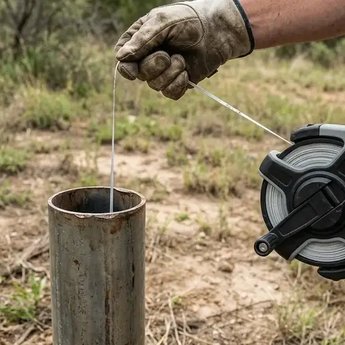
- Static water level (SWL) is the water level in the borehole when the pump has been off long enough for the level to recover. You can measure it with a water level dipping tape or sounding device.
- Drawdown is the drop in water level from the static level once pumping starts: the aquifer is being extracted faster than it recharges, so the level around the pump falls. Drawdown is the difference between the static and dynamic levels.
- Dynamic water level (DWL) is the water level during pumping at the target flow rate: DWL = SWL + drawdown. This is the number you use in TDH, not the static level.
- Elevation above ground is the vertical distance from the wellhead up to the tank inlet, reservoir surface, or sprinkler outlet.
- Friction loss is the head lost to the pipe walls between the pump discharge and the delivery point. It grows with flow rate, pipe length, pipe roughness, and every fitting, valve, or elbow.
- Delivery pressure head is the pressure the water needs at the point of use, converted to meters of water column. One bar equals about 10.2 m of head; one psi equals about 2.31 feet.
A critical distinction that prevents expensive mistakes: pump setting depth is not TDH. You install the pump below the dynamic water level so the intake stays submerged, but TDH is figured from the dynamic water level itself, not from where the pump physically hangs. Calculating TDH from setting depth overestimates the lift by the submerged depth of the pump.
For complex piping layouts with long horizontal runs, multiple branches, or unusual fittings, the friction loss term deserves a deeper calculation than this section can hold. If those runs matter on your site, use the full method in the guide on calculate Total Dynamic Head (TDH) before you commit to a pump.
A working field measurement is the reliable way to populate the first two rows of this worksheet:
A worked example keeps this honest. Suppose a livestock borehole needs 15 m³/day, the site has 5 PSH, so the target flow is 3 m³/h. The static water level measures 35 m and a pump test shows 8 m of drawdown at that flow, so the dynamic water level is 43 m. Water must be lifted another 10 m above ground into a storage tank, and friction loss on the discharge line is 5 m. No discharge pressure is required because the tank is open:
TDH = 43 m + 10 m + 5 m + 0 m = 58 m
The pump must deliver 3 m³/h at 58 m TDH. Those two numbers are the point where the pump curve gets matched.
You can lay the same calculation out field by field:
| Parameter | What it represents | Your measurement (m) |
|---|---|---|
| Static water level (SWL) | Water level when the borehole is fully recovered | |
| Drawdown at target flow | Drop in level once pumping starts | |
| Dynamic water level (DWL) | SWL + drawdown — the pumping water level | |
| Elevation above ground | Vertical lift from wellhead to discharge point | |
| Friction loss | Pipe wall and fitting losses at target flow | |
| Delivery pressure head | Required outlet pressure, converted to meters | |
| Total TDH | Sum of the rows above |
Step 3: Match the Pump Performance Curve, Motor Type, and Borehole Fit
You now have a flow and a head. The pump selection itself comes from the manufacturer's curve: find the curve that has your flow/head point sitting inside the pump's operating range, close to its best efficiency point, not out past the curve's left or right edge.
Reading a solar pump curve has one extra discipline versus an AC pump curve. The manufacturer's curve is usually shown for a defined solar input or a standard test condition. In real operation, the pump's available input changes throughout the day as irradiance rises and falls. That means the pump does not sit at one fixed duty point all day — it moves up and down the curve as the controller feeds it more or less power. You therefore want a selection with enough curve above and below the duty point that the pump keeps producing useful flow through morning and late afternoon, not a razor-thin selection that only works at solar noon.
There are two broad electrical architectures, and the choice shapes everything downstream:
- DC brushless direct-drive systems pair a permanent-magnet brushless motor with a matched solar pump controller. The controller performs motor commutation and can soft-start the motor as the array wakes up. These tend to be the default choice for remote livestock and small-to-mid irrigation where the water demand matches the solar window.
- AC submersible pump plus solar inverter uses an inverter to convert DC to AC and runs a conventional three-phase submersible motor. This can make sense where the project already standardizes on AC motors, where higher power or deeper multi-stage pumps are required, or where a hybrid solar/grid/generator supply is planned. Both architectures use power electronics; the practical differences are motor type, how commutation and inverter functions are integrated, voltage, depth capability, hybrid flexibility, and local service. Confirm the complete system efficiency, not the motor efficiency alone, before comparing quotes.
The selection decision table below separates the questions a buyer actually faces. Use it to shortlist, not to replace a manufacturer's confirmation.
| Decision factor | DC brushless direct-drive | AC submersible motor + solar inverter |
|---|---|---|
| Where it tends to fit | Remote, moderate-power boreholes where the demand is met fully in the solar window | Higher-power, deeper, or hybrid systems already standardized on AC motors |
| Part-load behavior | Matched pump controller handles motor commutation; pump follows available array power | Inverter must manage motor startup surge; confirm minimum operating power |
| Power electronics | Dedicated solar pump controller performs motor commutation and soft start | Separate solar inverter supplies the AC motor; confirm startup behavior and total system losses |
| Cable voltage and voltage drop | Often lower DC voltage, so drop matters more | Often higher AC voltage, so drop is easier to manage on long runs |
| Maintenance and spares | Motor and controller usually bought as a matched set | Standard AC motor can simplify local spares and service |
Don't select architecture from a catalog photograph. Select it from motor type, voltage, depth, hybrid capability, local service capability, measured site conditions, and a hard conversation with the supplier about the entire electrical path and total system efficiency.
Borehole diameter is the mechanical gatekeeper. The pump body must slide down the casing with clearance around it, plus room for the supply cable and any cable guards. If the pump outer diameter is too close to the borehole's inside diameter, installation becomes a fight and casing damage becomes a real risk. A common convention is to leave enough radial clearance that the pump can be lowered and retrieved without scraping — as a picture, a 4-inch pump is routinely paired with a 5-inch or larger borehole, but you must confirm the exact pump OD against your casing ID with the selected model, not from a rough rule. For details beyond the solar electrical side, the mechanical selection factors are covered in the broader submersible water pump selection guide.
Step 4: Size the Solar Array (Wp) and MPPT Controller
The panel array exists to supply enough DC power at the controller input through the worst hours and temperatures you actually expect, not just at a single perfect test condition. Start with the pump motor's rated input power at the duty point, then add margin.
A practical first estimate is to provide 1.3 to 1.5 times the pump motor input power in panel watt-peak (Wp). The margin covers real-world losses that a datasheet cannot show: panel temperature derating in heat, module soiling, wiring and connection losses, controller conversion losses, and lower-than-test irradiance on hazy or cloudy days. In weak-irradiance regions, the required margin can be larger — some manufacturers may recommend going above 1.5 times rather than risk the pump falling below its minimum operating point. Treat the ratio as a starting number to be confirmed, never as a substitute for the manufacturer's specified array.
Worked example for the livestock borehole above: if the pump selected at 3 m³/h and 58 m TDH has a 1.1 kW motor input power, a 1.3 to 1.5 margin gives a first-pass array of roughly 1.43 to 1.65 kWp. Using readily available 400 Wp modules, that rounds to four modules, or 1.6 kWp — a sensible starting point to confirm with the controller's voltage window.
MPPT controller sizing has two separate limits that get mixed up:
- Power/current rating must cover the array at its maximum output and the motor's running current.
- Voltage window must accept the array's open-circuit voltage (Voc) at the site's coldest morning temperature, not at standard test conditions. Cold panels produce higher voltage, and an under-rated controller can fail on a clear, cold morning when you most need the pump.
Ask the supplier for the controller's maximum PV input voltage and then have them verify the panel string's cold-weather Voc against it. This single check catches a class of avoidable field failures that don't show up in a sales quote.
On the module side, panels should carry a recognized design-qualification standard such as IEC 61215. On the controller side, Indian projects and several government procurement programs reference IS 16221 (Part 2) for solar photovoltaic water pumping controllers. Don't accept a supplier who just says "certified" without naming the standard and showing the certificate number.
Step 5: Cable Sizing and Voltage Drop Over Deep Wells
Cable sizing is where depth quietly destroys performance. The conductor path is not the borehole depth — it is twice the depth, because current flows down to the motor and back through the return conductor. A pump set 100 m down has a round-trip conductor path of roughly 200 m.
The physical law is straightforward: voltage drop rises with current and cable length, and falls as conductor cross-section increases. Lower-voltage DC systems are punished hardest because the same absolute drop is a larger percentage of a smaller system voltage. A 3-volt drop on a 48 V system is a much bigger deal than 3 volts on a 380 V system.
Keep voltage drop at the motor terminals under about 3% — and confirm the manufacturer's specific limit, because some controllers and motors are less tolerant. A pump running on low terminal voltage produces less flow, runs hotter, and shortens motor life. The cable that "works" for a short test run can fail you on a hot afternoon at full power.
The following table is an indicative starting point for planning, not a substitute for calculation. Temperature, actual motor running current, cable type, and allowable voltage drop all change the answer.
| Example motor setup | One-way borehole depth | Starting copper cross-section to check |
|---|---|---|
| Small DC brushless, ~0.37 kW, 48 V nominal | 40 m | 6 mm² (about 10 AWG) |
| DC brushless, ~0.75 kW, 72 V nominal | 80 m | 10 mm² (about 8 AWG) |
| AC submersible via inverter, ~1.1 kW, 110–220 V | 100 m | 4–6 mm² (about 12–10 AWG) |
| AC three-phase, ~4 kW, 380 V | 200 m | 6 mm² or larger (about 10 AWG) |
Don't accept a quote that simply says "cable included" without a conductor cross-section and a voltage-drop calculation for your depth, voltage, and current.
Two more field realities matter beyond gauge:
- The underwater splice. The submersible pump usually arrives with a motor lead that must be joined to the drop cable down the hole. That connection must be fully waterproof — an IP68-rated encapsulation kit or factory-made splice designed for continuous submersion, not tape and shrink tube exposed to well water.
- The cable-to-drop-pipe attachment. On a deep borehole, the cable must be strapped at regular intervals so its own weight and pulling do not stretch the conductors, crack the splice, or abrade insulation against the casing. A cable that hangs free from the motor is a running failure.
Essential Protections: Dry-Run, Over/Under-Voltage, and Sand Tolerance
A remote solar pump can fail years early for reasons that have nothing to do with the sun. One of the most expensive is dry running.
When the pumping water level drops below the intake — either from seasonal drawdown, an overdrawn aquifer, or a well that has simply recovered slower than the pump can pull — the motor loses its cooling path and the hydraulic parts run without water. Water-lubricated motors and bearings are particularly exposed. The prevention is not magical; it is an electrode probe, float-level switch, or integrated dry-run detection in the controller that stops the motor before damage occurs. Ask the supplier exactly which dry-run protection comes in the quote and how it is wired, because "dry-run protected" is one of the most loosely used phrases in this market.
Specify the motor enclosure and cable entry as IP68-rated for the actual submersion depth, and ask the supplier to confirm the depth rating on the datasheet. A pump can be "waterproof" for a shallow tank and still fail at 100 m if the seals and cable entry are not rated for that pressure.
Over-voltage and under-voltage protection should be inside the controller or provided by dedicated devices. Over-voltage arrives on cold bright mornings when the array produces more than the controller can safely accept; under-voltage arrives in late afternoon, on heavy clouds, or on an undersized cable. The controller's low-voltage cutoff keeps the pump from stalling and overheating; the high-voltage cutoff protects the electronics themselves. Confirm both limits on the controller datasheet, and match them to your array's cold-weather voltage range.
Sand and abrasive content is the borehole-specific wear problem. Even low sand concentrations, pumped daily, erode impellers and diffusers over a season. Two defenses: select a pump and impeller materials rated for the measured sand content, and keep the flow velocity reasonable so sand does not act like a sandblaster inside the pump. If the borehole shows sand on a pump test, say so plainly in the RFQ — a supplier cannot quote the right materials if you hide the water quality. For a deeper treatment of what sand, dynamic level, and borehole yield mean for long-term reliability, the pump for borehole water supply guide covers the water-source side in more detail.
On protection generally, IEC 62253 is a key standard to have on the table. It defines design qualification and performance measurement for photovoltaic pumping systems, so asking whether the pump and system are tested to IEC 62253 turns "it works with solar" from a claim into a verifiable test condition.
Common Solar Submersible Pump Sizing Mistakes
These are the failures that come back as warranty claims, project disputes, and dry-season emergencies. Check your own numbers against each one before you send the RFQ.
- Ignoring drawdown. Using the static water level instead of the dynamic water level understates TDH, so the pump moves less water than expected — and if drawdown is severe, the intake runs dry during the hottest hours.
- Undersizing the solar array. A pump that barely reaches its minimum operating point on a clear day produces nothing useful on a hazy day. The margin is not optional.
- Wrong cable gauge. An undersized conductor over a deep round trip drops voltage, reduces flow, and heats the cable and motor. The fix is a new cable down the hole, which means pulling the pump — an expensive rework.
- Selecting from the AC-grid pump curve. The same pump's output under variable solar input is not the same as its output at constant grid voltage. Select from the solar operating curve.
- Ignoring borehole yield. If the pump extracts faster than the aquifer recharges, the well runs dry and the pump cycles or burns. A pump test result is part of the sizing data, not a nice-to-have.
- Pulling the cable freely against the drop pipe. On a deep well, an unsupported cable stretches, chafes, or cracks the submerged splice.
- Mismatching panel string voltage to the controller. Cold-morning Voc above the controller maximum can kill the controller, not the panels. This is one of the most avoidable electronics failures in the field.
- Sizing the storage tank from pump flow alone. If the tank only holds a few hours of output, any extended cloudy period becomes a water shortage even when the pump itself is fine.
Supplier Verification: Questions That Separate Real Specs From Sales Talk
Before you settle on a supplier, ask for evidence, not opinions. The answers below tell you more than the brochure ever will.
- Request the solar-specific performance curve, with the head/flow points stated for the actual solar operating window, not a constant-grid test result.
- Ask for the controller's maximum PV input voltage and the array string Voc at the site's minimum temperature.
- Ask for the motor and pump test or inspection report — performance test, pressure test, dimensional check, and any dynamic balance record where applicable.
- Ask for material certificates for the components that touch water: housing, impellers, diffusers, and cable sheath. If you order 304 or 316 stainless steel, get the mill/heat traceability, not a verbal confirmation.
- Ask for the cable splice rating. A fully submersible waterproof splice or a factory motor lead is the difference between a pump that lasts and a pump that fails at the joint.
- Confirm the dry-run protection method in writing, including where the sensing element is mounted.
- Ask for the relevant compliance documents: IEC 62253 for the pumping system, IEC 61215 for modules, and IS 16221 (Part 2) for controllers where that market standard applies.
- Check the warranty's misuse exclusions, especially around dry running, sand abrasion, and lightning/surge damage. A short or heavily conditioned warranty is a cost signal, not a detail.
Verification does not end at the quote. For any sizable order, a pre-shipment inspection or a third-party factory test is one of the cheapest forms of insurance you can buy against receiving a pump that never saw the curve the datasheet promised.
RFQ Checklist: What to Send Your Solar Pump Supplier
This is the copy-paste block for a serious quote request. Fill every field you can; write "to confirm" where you do not yet have data.
| Field | What to provide |
|---|---|
| Application | Irrigation, livestock, or remote water supply |
| Daily water demand | Target m³/day, plus any peak-day margin |
| Required flow rate | m³/h, calculated from daily demand ÷ PSH |
| Peak Sun Hours | Site PSH and the data source or season used |
| Borehole diameter | Inside diameter in inches or mm |
| Borehole depth | Total drilled depth and pump setting depth |
| Static water level | Measured depth to water, in meters |
| Dynamic water level or drawdown | From a pump test at the target flow, or "test required" |
| Water quality | Clear, sandy, salinity/pH/TDS if known, and temperature |
| Discharge point | Elevation above ground, pipe material, diameter, and total pipe length |
| Required discharge pressure | In bar or psi at the delivery point, if any |
| Preferred electrical architecture | DC brushless direct-drive or AC submersible plus inverter |
| Available panel Wp and module size | Or "supplier to specify" |
| Cable length | Full down-and-back conductor path |
| Required protections | Dry-run detection, over/under-voltage, surge protection |
| Standards | IEC 62253 for system, IEC 61215 for modules, IS 16221 (Part 2) for controllers where applicable |
| Target quantity and packaging | Units, export packaging, and any OEM/branding requirements |
| Documents requested | Test reports, material certificates, controller settings, warranty terms |
Sending this once beats three rounds of back-and-forth clarification. A supplier who does not care about drawdown, water quality, or cable voltage drop at the RFQ stage will not suddenly care after payment.
FAQ: Solar Submersible Pump Sizing
These are the long-tail questions buyers ask when they are already past the "what is a solar pump" stage and into the actual calculation.
How do I start a solar submersible pump sizing calculation?
Start with daily water demand in cubic meters per day, then divide by the site's average Peak Sun Hours to get the required flow rate in cubic meters per hour. Do not start with panel wattage or motor power — those come after the hydraulic point is defined.
How do you calculate Total Dynamic Head (TDH) for a deep well?
TDH equals the dynamic water level plus the elevation above ground to the discharge point, plus friction loss in the pipe, plus any required delivery pressure converted to meters. The dynamic water level is the static water level plus drawdown, so you must have a pump test or reliable drawdown estimate before TDH is meaningful.
How many solar panels do I need for a submersible pump?
Begin with 1.3 to 1.5 times the pump motor's rated input power in panel watt-peak, then confirm the array voltage window against the controller's maximum PV input voltage at the site's coldest temperature. The actual number of panels depends on the module wattage you buy and the site's irradiance; a weak-irradiance site can require a larger margin.
What cable size is needed for a 100 m deep well pump?
There is no single correct answer without the motor voltage and running current, because the cable must handle a roughly 200 m round-trip conductor path. A low-voltage DC motor pumping 100 m deep will generally require a substantially larger copper cross-section than a higher-voltage AC motor at the same depth; always have the supplier calculate voltage drop for your exact current and confirm it stays under about 3%.
Can a solar borehole pump run on cloudy days?
A direct-drive solar pump will not run at full output under heavy cloud, but a well-sized system keeps the pump above its minimum operating point through moderate haze and partial cloud. The practical answer is to design storage capacity for cloudy-day buffers rather than expect the pump to maintain rated flow without sun.
How do I protect a solar submersible pump from running dry?
Use an electrode probe, float switch, or integrated dry-run detection in the controller to stop the motor when the water level drops below safe intake depth. Confirm the protection method in writing and where the sensor is mounted before you accept the quote.
Official Sources and Compliance References
This guide references three documents that give the buyer independent verification points:
- IEC 62253 covers design qualification and performance measurement of photovoltaic pumping systems. It is the standard to cite when you want the supplier to prove the pump is tested under solar-specific conditions.
- IEC 61215 is the design qualification and type approval standard for terrestrial photovoltaic modules, covering the environmental and mechanical stresses modules must survive.
- IS 16221 (Part 2) is referenced in India for solar photovoltaic water pumping system controllers, and often appears in procurement or subsidy-documentation requirements for that market.
Ask for the certificate or test report that corresponds to your market and installation environment; none of these standards guarantees a good selection by itself, but they give you a shared, auditable language with the supplier.
Conclusion: Your Sizing Order of Operations
Hand the numbers to a supplier in this order and the quote will actually match the field: demand to flow, flow to TDH, TDH to pump curve, pump to array and controller, controller to cable voltage drop, and finally to the protections — dry-run, voltage limits, and sand tolerance. That sequence is the whole job. Skip an early step and each later number inherits the error.
Measure the static and drawdown levels at the wellhead, not from memory. Check the borehole yield before the pump flow. Confirm the cold-morning array voltage before the controller is ordered. When the RFQ leaves your desk with those numbers in place, both you and Liqen's team can review the same facts — and the difference between a system that survives multiple dry seasons and one that dies in the first hard dry season has usually already been decided at the calculator.
Get A Quote

Get A Quote
0 Comments