
How to Reduce Wear in Slurry Pump and Slurry Pipeline Systems
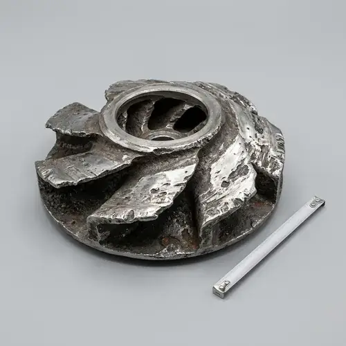
Effective slurry pump wear reduction isn’t about finding a magic material. It’s about controlling slurry velocity, keeping the pump near its best efficiency point, choosing liner and pipe materials that match your actual particle size and chemistry, and designing pipe routing that avoids concentrated impact zones. In many field applications, systems fail early because the pump was sized for flow alone, settling velocity was ignored, or a “wear-resistant” material label was selected without checking whether it fits corrosive or coarse-slurry conditions.
Unplanned wear in abrasive slurry handling turns into unscheduled shutdowns, high spare-part consumption, and maintenance crews chasing the same failed elbow or liner every few months. This guide gives you a system-level reliability framework—velocity thresholds, material-selection boundaries, pump operating-point checks, pipeline geometry rules, inspection intervals, and an RFQ checklist you can use today—so you spend less on emergency repairs and more time moving slurry.
Bookmark this page as your engineering reference. Email it to your maintenance lead and your pump supplier. Use it before you approve the next pump selection or pipeline routing change.
Quick Answer: How to Reduce Slurry Wear in 30 Seconds
Slurry pump wear reduction comes down to five controls, ranked by impact:
- Reduce slurry velocity inside the pump and pipeline—erosion rate scales with velocity raised to roughly 2.5–4.5. Cutting speed by 20% can often substantially reduce wear; in many systems, wear may drop by half or more, though the exact improvement depends on your slurry.
- Operate the pump between 80% and 110% of BEP—off-BEP recirculation and cavitation chew through impellers faster than abrasive particles alone.
- Match liner material to particle size, hardness, and pH—high-chrome iron handles coarse, hard solids; rubber handles fine, rounded particles in non-corrosive service; ceramics survive extreme fines but crack under impact.
- Use long-radius bends (3D minimum, 5D preferred) and proper reducer orientation to spread particle impact over a larger area and eliminate dead zones.
- Monitor liner thickness and vibration trends so you replace wear parts on a schedule, not after a failure.
If you change nothing else, lower the velocity and confirm the pump is running at BEP. In many slurry systems, those two changes reduce slurry pipeline wear more effectively than a liner upgrade alone.
Scope of This Guide
This page covers slurry transport systems in mining, mineral processing, dredging, and industrial waste handling—anywhere you are pumping a mixture of liquid and abrasive solids through centrifugal slurry pumps and connected steel or lined pipelines.
This guide covers: - Abrasive, erosive, corrosive, and cavitation wear mechanisms and how to tell them apart - Velocity selection rules for pumps and pipes, including critical settling velocity trade-offs - Pump operating point and its direct effect on wear rate - Impeller, volute liner, and pipeline material selection—metal, rubber, polyurethane, ceramic - Pipeline routing, bend geometry, and reducer orientation - Inspection and preventive maintenance that reduces spare-part consumption - Supplier verification and the technical data you must include in an RFQ
This guide does not cover: - General centrifugal pump theory - Clean-water or municipal sewage pumping - Slurry pump mechanical seal design in detail (that belongs in a dedicated seal guide) - Mining process control beyond slurry transport
If you are selecting a pump from scratch, pair this page with our slurry pump selection and wear analysis guide to build a complete hydraulic and material specification.
Why Slurry Systems Wear Faster Than Standard Pump Systems
A clean-water pump running at BEP can operate for years with minimal internal damage. A slurry pump handling 30% solids by weight can eat through a volute liner in months—sometimes even faster—if the velocity, material, or hydraulic fit is wrong. The difference isn’t just the presence of solids. It’s the combination of mechanical abrasion, fluid erosion, corrosion, and cavitation, often attacking the same surface at the same time.
Most slurry wear failures in field investigations aren’t caused by one mechanism working alone. You get erosion cutting a groove into a rubber liner, corrosion softening the metal underneath, and then cavitation popping out chunks of the already-weakened surface. The repair crew sees a hole, calls it “wear,” and orders the same spare part. The root cause stays hidden.
Abrasion vs Erosion vs Corrosion vs Cavitation
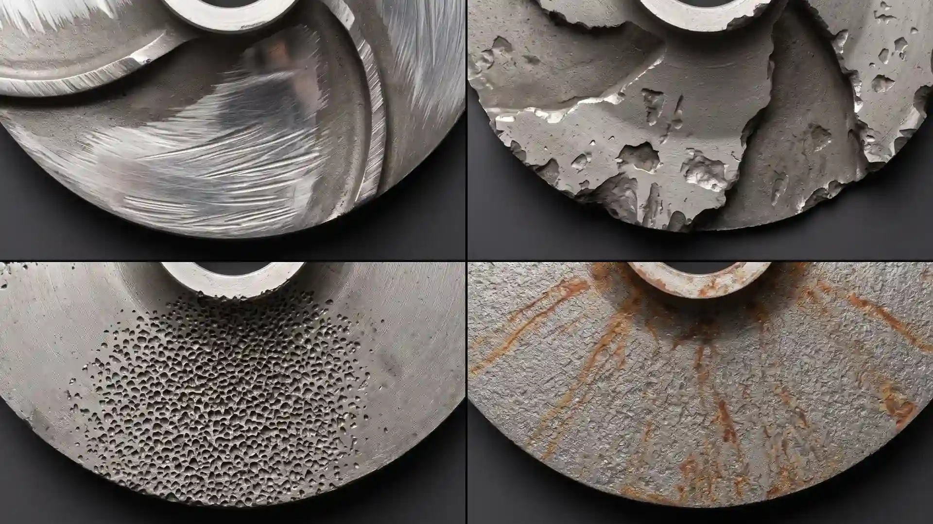
All four mechanisms show up in slurry systems, but they look different, attack different locations, and require different countermeasures.
Abrasion is low-angle particle rubbing—fine solids sliding across a surface under pressure, polishing it away. In a slurry pump you see this on volute cutwaters, impeller shrouds, and suction liners. High-chrome iron resists abrasion well because of its hardness; rubber resists it poorly at high sliding speeds because it heats and tears.
Erosion is high-angle particle impact—coarse solids hammering a surface, chipping out material. This dominates in pump impeller blade leading edges and the outer wall of pipe elbows. Erosion rate is sensitive to velocity and particle kinetic energy. That’s why slowing the pump down helps more than thickening the liner.
Corrosion is electrochemical attack from acidic or alkaline slurry chemistry. Low pH process water (common in copper and gold processing) can corrode cast iron liners even if particle wear looks mild. Corrosion often accelerates abrasion because it roughens and weakens the surface. If your slurry pH drops below 4, you need to re-evaluate metal liner selection and consider duplex stainless steel or rubber-lined options.
Cavitation is vapor bubble collapse—not a solids problem at all, but frequently misdiagnosed as abrasion. When the pump’s NPSH available is too low, vapor bubbles form at the impeller eye and collapse violently against the blade surface, producing a sponge-like pitting pattern. In some field cases, operators replace impellers repeatedly for “abrasive wear” before discovering the actual cause was a clogged suction strainer starving the pump inlet and reducing NPSH margin below the requirement.
The table below gives you a field reference for what you’re seeing and where to start fixing it.
| Wear Mechanism | What It Looks Like | Common Location | Primary Mitigation |
|---|---|---|---|
| Abrasion | Smooth, polished surface with directional scoring | Volute cutwater, impeller shrouds, suction liners | Increase material hardness (high-chrome iron), reduce sliding velocity |
| Erosion | Sharp-edged gouges, undercut pits at impact angles | Impeller blade leading edges, outer radius of elbows | Reduce velocity, increase bend radius, use impact-resistant liner |
| Corrosion | Uniform grainy etching, orange/brown rust or pits with corrosion product | Any wetted surface, especially in low-velocity zones | Match material to pH, consider rubber or duplex stainless |
| Cavitation | Sponge-like clusters of small sharp pits, often near impeller eye | Impeller blade suction side near inlet | Fix suction piping, increase NPSH margin, reduce pump speed |
Velocity Control Is the Most Important Wear Reduction Variable
Across most slurry systems, velocity control is the single biggest lever for reducing slurry pump wear. Erosion rate is not proportional to velocity—it’s proportional to velocity raised to a power between about 2.5 and 4.5, depending on particle size, impingement angle, and material. That means a 10% speed increase doesn’t produce 10% more wear—it can produce 40–60% more wear. Cut velocity the other way, and you get a disproportionately large gain.
Slurry velocity in the pipeline directly controls whether solids stay suspended or settle out. If velocity is too high, pipe walls and pump wetted parts erode fast. If velocity is too low, solids drop out of suspension and form a stationary bed that can plug the line or cause localized corrosion under the settled solids. You have to hit a narrow window.
Why High Velocity Increases Erosion Exponentially
Every particle traveling through a pipe carries kinetic energy proportional to its mass times the square of its velocity. When that particle hits a bend wall or impeller vane, the energy dissipates into the material surface. Double the velocity, and you roughly quadruple the impact energy of each particle. Erosion models in slurry transport commonly use a velocity exponent between 2.5 and 3.5 for ductile materials (rubber, mild steel) and closer to 3.5–4.5 for brittle materials (high-chrome iron, ceramic). That’s the physics behind why small speed reductions can meaningfully extend liner life.
In field applications, operators have reduced pump impeller tip speed from around 28 m/s to 22 m/s and significantly extended impeller service life—sometimes doubling it—without changing the impeller material. Tip speeds above 25 m/s for coarse slurry (plus-5 mm particles) are asking for trouble unless you’re using thick high-chrome liners and have accepted high spare-part consumption as part of the operating budget.
The Risk of Operating Below Settling Velocity
Slowing down to reduce erosion sounds smart until the solids stop moving. Each slurry mixture has a critical settling velocity—the minimum average pipe velocity needed to keep particles suspended. If you drop below it, solids begin settling on the bottom of horizontal pipe runs. This creates three problems:
- The effective pipe cross-section shrinks, raising velocity in the remaining open area and accelerating erosion at the top of the settled bed.
- Stationary solids can cause under-deposit corrosion if the slurry is chemically aggressive.
- A full blockage stops production completely—and clearing a plugged slurry line is far more expensive than replacing a worn elbow.
Critical settling velocity isn’t a fixed number. It depends on particle size distribution, solids specific gravity, solids concentration, pipe diameter, and carrier fluid viscosity. For many mining slurries with a D50 around 200–500 microns, the settling velocity falls in the 1.5–2.0 m/s range, but you must calculate or test it for your specific slurry. Don’t just copy a number from another site that handles a different ore body.
The operational window is narrow: above critical settling velocity, but below the velocity where erosion becomes the dominant life limiter. A well-designed abrasive slurry handling system targets 1.5–3.0 m/s for most mineral slurries in steel pipes, adjusting upward for coarser particles and downward for finer, less abrasive solids.
Engineering note: velocity limits, NPSH checks, settling-velocity guidance, and bend-radius practices in this article should be verified against project-specific calculations and recognized references such as ANSI/HI pump standards and slurry application guidance, ASME piping design practices, and established slurry transport correlations including Durand-type settling methods.
Reference sources commonly used by slurry-system engineers include ANSI/HI 12.1-12.6 Rotodynamic (Centrifugal) Slurry Pumps, ANSI/HI 9.6.1 guideline concepts for NPSH margin assessment, ASME B31.3 process piping practices, and standard slurry transport correlations published in mineral processing and hydraulic transport engineering literature.
| Parameter | Typical Guidance (Verify for Your Slurry) | Notes |
|---|---|---|
| Minimum pipeline velocity | 1.5–2.0 m/s for settled solids prevention | Must be confirmed via Durand or similar correlation; varies with PSD and SG |
| Maximum pipeline velocity (steel pipe, coarse solids) | ~3.0–4.0 m/s before erosion accelerates sharply | Above ~4 m/s, wear rate climbs rapidly for typical abrasive slurries |
| Maximum pipeline velocity (rubber-lined pipe) | Check manufacturer limit; often lower than steel | Rubber may erode faster at high velocity and with sharp particles |
| Impeller tip speed (coarse slurry) | ≤ 25 m/s; many operators target 18–22 m/s | Higher speeds acceptable with hard metal liners and accepted wear rate |
| Impeller tip speed (fine/light slurry) | 20–30 m/s depending on material | Assess based on impeller material and slurry abrasivity |
When Lower Pump Speed Improves Total Lifecycle Cost
Reducing pump speed doesn’t just lower wear—it reduces power consumption (power scales with the cube of speed), bearing loads, and vibration. A VFD installation that lets you trim 10–15% off pump speed when process conditions allow often pays back in under two years from electricity savings alone, and the wear reduction is a valuable bonus on top.
The caution: if you lower pump speed, make sure the pump can still generate enough head to meet your system curve and keep pipeline velocity above the settling limit. That requires a system curve calculation, not a guess. See our pump system design and pipe sizing guide for the head-loss calculation method.
How Pump Operating Point Affects Slurry Wear
Buying a pump with heavy-duty liners and then running it at 50% of BEP flow is like buying a truck rated for off-road hauling and only driving it in first gear on the highway. The components are right but the operating condition is wrong, and wear will be faster than you expect.
When a centrifugal pump operates away from its best efficiency point, internal flow patterns change. At low flow, recirculation vortices form at the impeller eye and at the discharge cutwater. These vortices trap particles and spin them against the same surfaces repeatedly, causing concentrated wear that has nothing to do with the overall pipeline velocity. At high flow, NPSH available drops and cavitation risk rises.
Off-BEP operation also increases radial thrust on the shaft, which wears bearings and mechanical seals faster. A bearing failure that forces an unplanned shutdown is often more expensive than the worn impeller that triggered it.
Wear Patterns Caused by Off-BEP Operation
After several months of operation, liner wear patterns often indicate where a slurry pump has been operating relative to its curve.
- Continuous operation below 60% of BEP: heavy wear on the pressure side of the impeller blades near the shroud, volute tongue erosion, and suction-side recirculation scoring. The cutwater looks like someone hit it with a chisel.
- Continuous operation above 120% of BEP: cavitation pits on the impeller eye suction side, plus evidence of suction piping vibration. The impeller leading edge may show a classic sponge pattern.
- Operation within 80–110% of BEP: wear is more uniform around the volute circumference. Components still wear, but at a predictable rate that lets you plan liner rotation and replacements.
If you’re using a VFD to manage flow rate, don’t assume variable-speed operation always helps wear. Slowing the pump down shifts the BEP proportionally, so the pump can still operate near BEP at a lower speed—that’s good. But if you slow the pump without adjusting the system curve, you may push the operating point further from BEP and make wear worse even as velocity drops.
Cavitation Damage Often Misidentified as Abrasion
In mining and industrial slurry systems, this is one of the most common and expensive wear-related misdiagnoses. A maintenance planner sees pitting on an impeller, writes “abrasive wear” on the work order, and installs a harder impeller. The harder impeller fails in the same way, because the root cause is insufficient NPSH margin, not insufficient hardness.
Cavitation in slurry pumps is trickier to detect than in clean-water pumps. The classic “popping” sound is often masked by solids impact noise. The damage pattern is your best clue: cavitation pits tend to cluster in honeycomb-like groups on the suction side of impeller blades near the inlet, while erosion damage is concentrated on the pressure side and at impact angles.
Before ordering another impeller, check suction pipe diameter (is it smaller than the pump suction flange?), strainer condition, sump level stability, and whether the pump speed was increased during the last “capacity improvement” project. An energy audit for industrial pump systems that includes NPSH verification is cheaper than a single unplanned impeller swap. Read our energy audit guide for industrial pump systems for a field measurement approach.
Selecting Wear-Resistant Materials for Slurry Pumps and Pipelines
Material selection is where theory meets the real slurry—and where a lot of buyer decisions go wrong. A supplier says “high-chrome liner” and the buyer assumes it will work, without checking particle size, pH, or impact angle. Then the liner fails in three months and the buyer blames the supplier. In reality, no single material covers every abrasive slurry handling condition.
Your material choice is a three-way trade-off between abrasion resistance, impact toughness, and corrosion resistance. Materials that excel at one property are usually weak at another. High-chrome white iron is extremely hard and abrasion-resistant, but it’s brittle—a large rock impact can crack it. Rubber absorbs impact energy well and resists many corrosive fluids, but high-velocity sharp particles can slice through it. Ceramics offer extreme hardness for fine-particle slurries but fracture under coarse-particle impact.
Metal Liners vs Rubber Liners
This is one of the most common slurry material-selection decisions, and the answer is almost never “one is better.” It’s “one is better for your specific slurry conditions.”
High-chrome white iron (ASTM A532 Class III) is the workhorse for coarse, hard, sharp particles—think mill discharge, primary cyclone feed, and heavy tailings. It has a Brinell hardness typically in the range of 550–650 HB in the as-cast, heat-treated condition, and it resists sliding abrasion well. Its limits: it’s brittle (low fracture toughness), it corrodes under acidic conditions (pH below approximately 4–5 depending on alloying and temperature), and it’s heavy—harder to handle during maintenance.
Natural rubber liners (typically soft natural rubber, 35–45 Shore A) work well in fine-particle slurries—typically sub-300 micron—where particles are rounded rather than sharp. Rubber absorbs impact energy, resists many corrosive chemicals, and handles fluctuating loads without cracking. Its limits: sharp or angular particles can cut rubber; high velocities above roughly 3.5 m/s in pipe can erode rubber quickly; and certain process chemicals (strong oxidizers, solvents, oils) degrade natural rubber. Rubber-lined pumps usually have a maximum temperature around 60–70°C, above which the rubber softens and loses wear resistance.
Polyurethane sits between rubber and metal. It offers better cut resistance than natural rubber and better impact resistance than high-chrome iron. It works well in medium-particle slurries where some impact plus some sliding wear is present. Polyurethane is sensitive to hydrolysis in hot, wet, alkaline conditions—above about 50°C in high-pH water, polyurethane can degrade chemically.
When Ceramic or Composite Liners Make Economic Sense
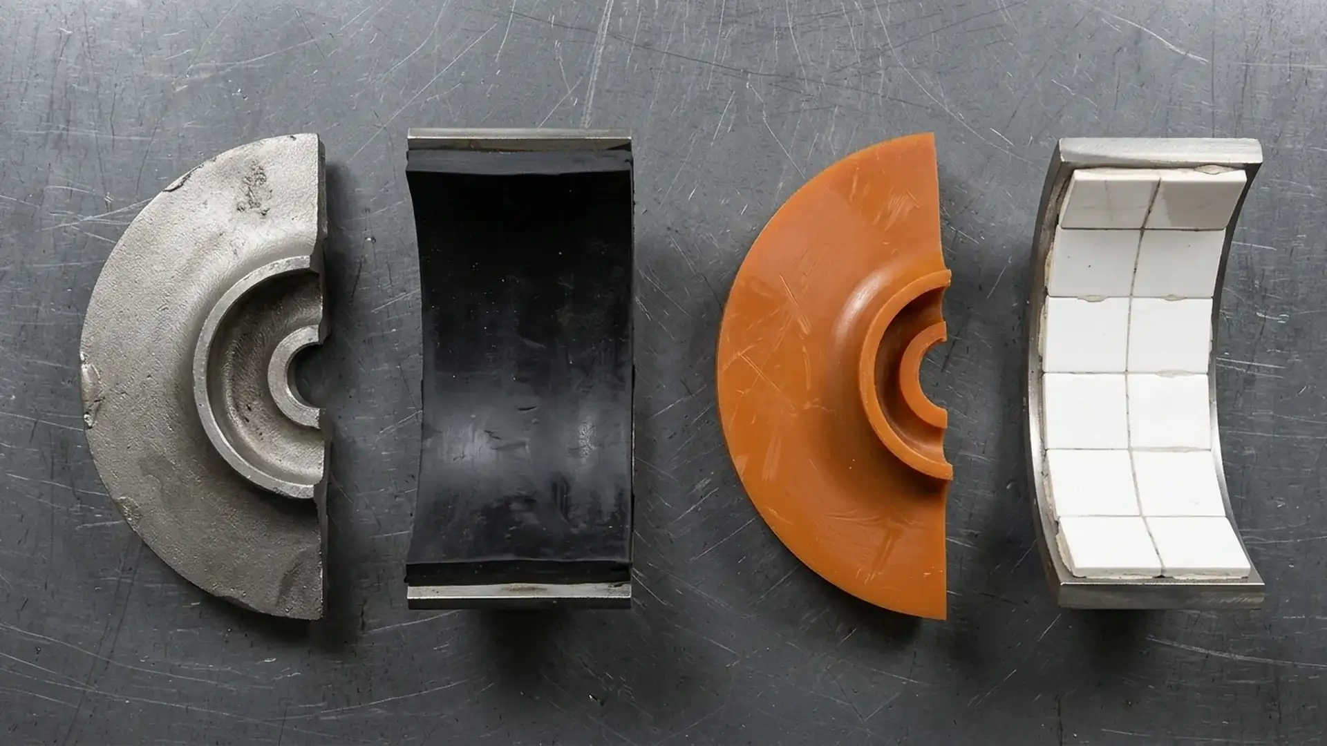
Ceramic liners—typically alumina or silicon carbide tiles bonded into a pump casing or pipe elbow—offer extreme hardness (often 1,200–1,500+ HV, well above white iron) and excel in high-velocity fine-particle erosion, such as flue gas desulfurization (FGD) slurry in power plants.
The trade-off is cost and fragility. Ceramic-lined pumps and elbows are significantly more expensive than metal or rubber alternatives. A single large-particle impact can crack a ceramic tile, and once a tile cracks and starts to spall, the underlying metal shell erodes rapidly. Ceramic liners also require careful installation—tile edges must be flush to avoid turbulence and edge erosion. In the right application (fine, consistent particle size, no tramp oversize, moderate temperature), ceramics deliver extremely low wear rates and long service intervals.
| Material | Best For | Particle Size Range | Impact Resistance | Corrosion Resistance | Relative Cost |
|---|---|---|---|---|---|
| High-chrome white iron | Coarse, hard, sharp particles; mill discharge | > 500 µm typical, large solids | Low (brittle) | Poor in acidic (pH < ~4–5) | $$ |
| Natural rubber | Fine, rounded, non-cutting solids; moderate pH | < 300 µm typical, sub-angular | High (absorbs energy) | Good in many chemicals; avoid oils/solvents | $–$$ |
| Polyurethane | Medium particles with some impact + sliding wear | 100–600 µm | Medium–High | Good, but sensitive to hot alkaline hydrolysis | $$ |
| Ceramic (alumina/SiC) | Fine, consistent particles, high velocity, no tramp oversize | < 200 µm, uniform | Very low (brittle) | Excellent in most slurries | $$$ |
The above is a selection starting point. You must confirm each material’s compatibility with your actual slurry chemistry (pH, temperature, chloride content, presence of solvents or oils) before placing an order.
Pipeline Routing and Bend Design to Reduce Erosion
Pipelines wear fastest where the flow direction changes. Bends, tees, and reducers force particles to change trajectory, and that directional change concentrates impact energy on a small surface area. A straight pipe section might last years while the elbow three meters downstream fails in months—because the straight pipe sees sliding abrasion and the elbow sees concentrated erosion.
Slurry pipeline wear is a geometry problem as much as a material problem. Changing the routing to reduce impact intensity can sometimes extend pipe life more than upgrading the pipe material.
Why Elbows and Reducers Wear First
When slurry enters a sharp bend, solids don’t follow the fluid streamlines smoothly. Coarse particles, which have more inertia, are thrown to the outside wall of the bend and impact at an angle. This impact is the main erosion driver. The tighter the bend, the more concentrated the impact zone.
Reducers present a different problem. A concentric reducer concentrates flow into a smaller cross-section and can create a dead zone behind the reduction step if oriented incorrectly. An eccentric reducer installed flat-side-up collects solids on the flat bottom and creates sliding bed wear; flat-side-down avoids this and is the standard for horizontal slurry lines.
Sudden expansions are even worse—the flow separates at the expansion step, forms a recirculation zone, and traps particles that grind away at the corner. Use long-taper reducers wherever possible.
How Long-Radius Bends Reduce Localized Impact
A 5D bend (radius = five times the pipe diameter) spreads the particle impact over a much larger arc than a standard 1.5D elbow. The peak impact pressure on any single point of the pipe wall drops significantly. In coarse-solids service—tailings lines, dredge discharge—5D bends are standard, and some operators even use 10D fabricated bends at critical locations.
The cost difference is real: a 5D bend uses more pipe material and takes up more space. But if the alternative is replacing a 1.5D elbow four times a year and shutting down the line each time, the 5D bend often pays back in the first year.
Other routing rules that reduce wear: - Avoid compound bends (two elbows in series with no straight run between them). The turbulence from the first bend throws particle trajectories off-axis, and the second bend catches the worst of it. Install at least 10 pipe diameters of straight run between direction changes. - Keep vertical risers as short as practical; if you must lift slurry, do it in one straight vertical section, not multiple sloped sections with intermediate elbows. - Inspect the outside radius of every bend as your first thickness-monitoring point.
Maintenance Strategies That Reduce Spare-Part Consumption
Reactive maintenance in abrasive slurry handling systems costs a lot more than planned replacements—often two to three times or more—when you factor in production downtime, overtime labor, expedited freight for spare parts, and collateral damage to seals, bearings, and shafts that happens when a worn component is run to failure.
A practical slurry pump maintenance strategy shifts from “replace when it leaks” to “replace when wall thickness reaches a defined minimum.” That requires two things: regular thickness measurements and a spare-parts inventory that matches your wear-rate data. Teams building formal inspection routes and shutdown planning procedures often integrate these checks into a documented preventive maintenance plan for industrial pumps so wear trends, vibration data, and spare-part consumption can be tracked together.
Inspection Intervals for High-Wear Components
The inspection interval depends on your measured wear rate, not on a generic monthly or quarterly schedule. Track wear for a few cycles, build a thickness-vs-hours chart, and then set your inspection and replacement intervals from real data.
| Component | What to Measure | Method | Typical Starting Interval (Adjust Based on Measured Rate) |
|---|---|---|---|
| Impeller | Blade thickness at leading edge, shroud thickness near eye | Ultrasonic thickness gauge; visual for cavitation pits | Every 500 operating hours or monthly |
| Volute liner / casing | Cutwater thickness, volute wall at 90° intervals | Ultrasonic thickness gauge; record on a casing map | Every 500 operating hours or monthly |
| Suction liner / throatbush | Bore diameter and wall thickness | Caliper or internal micrometer | Every 1,000 hours or quarterly |
| Pipe elbows (outer radius) | Wall thickness at 30°, 60°, 90° of bend arc | Ultrasonic thickness gauge; mark measurement points permanently | Every 1,000 hours or quarterly |
| Mechanical seal / gland packing | Leakage rate, flush pressure, temperature | Visual inspection daily; flush system check monthly | Daily visual; detailed monthly |
Which Spare Parts Should Be Stocked On Site
Stocking decisions are always a balance between downtime cost and working capital tied up in inventory. Slurry systems have a few components where the cost of not having the spare is vastly higher than the cost of the part itself.
Critical stock (unplanned failure stops production): - One complete rotating assembly (impeller, shaft, bearing assembly) per pump size - One set of volute liners and suction liner per pump - One complete mechanical seal cartridge - One set of casing gaskets and O-rings
Moderate priority (replaceable at planned shutdown): - Spare shaft sleeve - Throatbush - Bearing set (drive-end and non-drive-end) - Lantern ring / seal flush components
Low priority (available from supplier within lead time without stopping production): - Baseplate bolts - Coupling guard hardware - Instrumentation sensors
For a complete inventory planning approach that covers how to balance stock levels with lead-time risk, see our pump spare parts planning guide.
Supplier Verification and RFQ Checklist for Slurry Wear Applications
Buying a slurry pump or pipeline system for abrasive service is not a “send me your quote” transaction. If a supplier cannot discuss velocity limits, material hardness, and wear-rate factors specific to your slurry, their pump will probably wear faster than you expect—and their warranty fine print likely won’t cover it.
RFQ Data Suppliers Need Before Recommending Wear Materials
Send this data with every inquiry for abrasive slurry pumps or wear-resistant piping. If you skip a parameter, the supplier will assume a value—and their assumption may not match your process reality.
| RFQ Data Field | Your Input or TBD |
|---|---|
| Slurry description (e.g., “copper tailings, pH 8”) | |
| Solids specific gravity (SG) | |
| Solids concentration by weight (Cw %) | |
| Particle size distribution—D50 and D85 (microns or mm) | |
| Maximum particle size | |
| Particle shape (rounded, sub-angular, angular, sharp) | |
| Slurry pH and temperature (°C) | |
| Chloride content (ppm, if applicable) | |
| Required flow rate (m3/h or GPM) | |
| Total dynamic head (meters or feet) | |
| Static suction head or suction pressure | |
| Pipeline total length and inside diameter | |
| Number and type of bends (e.g., “4 x 5D long-radius, 2 x 45°”) | |
| Target pump operating hours per year | |
| Acceptable maintenance interval (e.g., “liner replacement every 8,000 hours minimum”) | |
| Power supply (voltage, frequency, phase) | |
| Site elevation and ambient temperature range |
Documents Buyers Should Request Before Approval
Before you approve a slurry pump supplier, ask for these documents—and actually read them. If a supplier is unwilling to share a performance curve or material certificate, treat that as a red flag.
- Certified pump performance curve—shows head, efficiency, power, and NPSHr across the full flow range, with the BEP clearly marked. Compare this against your system curve.
- Material certificates—mill test reports for the impeller and liner materials showing chemical composition and hardness. For high-chrome iron, confirm the hardness range and heat treatment condition.
- Hydrostatic test report—confirms the casing can withstand the maximum working pressure plus the required safety margin.
- Dynamic balance report—impeller balance grade (typically G6.3 or better for slurry pumps, depending on speed and size).
- Dimensional drawing—confirm flange standards, baseplate layout, and overall dimensions match your installation plan.
- Wear-life reference data—the supplier should be able to describe similar slurry applications where their pumps are operating, including the slurry type, estimated wear life of major components, and maintenance frequency. This is not a warranty—it’s an engineering reference point.
If your slurry application is particularly severe, discuss witnessed testing with the supplier. Hydrostatic and performance tests witnessed by your inspector or a third party add cost and lead time but provide confidence for large or critical installations.
FAQ
Below are common questions from maintenance engineers and procurement managers dealing with excessive erosion in slurry systems, along with concise field-oriented answers.
What is the biggest cause of slurry pipeline wear?
Excessive velocity is the primary accelerator. Pipeline erosion rate is roughly proportional to velocity raised to a power between 2.5 and 4.5, so even a 10% increase in flow rate can measurably increase wear. The second biggest cause is tight-radius elbows that concentrate particle impact on a small area of the pipe wall.
Can slower pump speed reduce slurry wear?
Yes, and it’s often the single most effective change you can make. Reducing impeller tip speed lowers both the velocity of solids impacting the impeller and the velocity inside the pipeline, disproportionately reducing erosion. The caution: you must maintain pipeline velocity above the critical settling velocity, and the pump must still generate enough head at the lower speed.
Are rubber liners suitable for coarse particles?
Generally no. Natural rubber liners work well with fine, rounded, non-cutting particles below roughly 300 microns. Coarse, sharp, or angular particles can cut rubber liners and accelerate failure. For coarse-particle slurries (mill discharge, crusher sumps), high-chrome white iron is usually a safer choice—unless the slurry is strongly acidic, in which case you may need to look at rubber or duplex stainless for corrosion resistance and accept some abrasive wear.
What bend radius is recommended for slurry pipelines?
For most industrial slurry transport, use 5D bends (radius equals five times the pipe diameter) as a minimum for coarse or highly abrasive solids. For finer, less abrasive slurries, 3D bends may be acceptable. Standard 1.5D elbows should be avoided in slurry service except for non-abrasive fluids. Install at least 10 pipe diameters of straight run between any two direction changes.
How do I know if cavitation is occurring?
Look for a sponge-like pitting pattern on the suction side of the impeller blades near the inlet eye—that’s the classic cavitation signature. A rattling or “gravel knocking” sound from the pump suction (hard to hear in slurry service, but detectable with vibration analysis), sudden drop in discharge pressure, and increased vibration at the pump suction bearing are additional indicators. Check suction pipe size, strainer condition, sump level, and NPSH margin before assuming the damage is abrasive wear.
Conclusion
Slurry pump wear reduction is a system-level problem, not a single-component fix. The highest-impact actions you can take, in priority order:
- Measure and control velocity. Confirm your pipeline velocity sits above the critical settling velocity and below the threshold where erosion accelerates sharply. Reduce impeller tip speed where head requirements allow. A VFD is often the fastest payback investment in a slurry system.
- Verify the pump operating point. If the pump is running below 60% or above 120% of BEP, internal recirculation and cavitation are chewing through components regardless of the liner material. Correct the hydraulic fit or adjust speed.
- Match materials to your real slurry properties. Don’t pick a liner based on a category label like “high-chrome” or “rubber.” Confirm particle size, shape, pH, temperature, and chloride content, and select the material that fits those specific conditions. Test one pump before you standardize across the fleet.
- Sort out your pipe geometry. Replace tight elbows with long-radius bends. Orient eccentric reducers flat-side down. Add straight runs between direction changes. The pipe routing you inherited from a clean-water design won’t hold up in slurry service.
- Track wear rates, not just failures. Use thickness measurements and vibration trends to set replacement intervals based on data, not calendar guesses. Keep critical spares on site so a liner change is a planned shutdown, not a crisis.
If you have the velocity right, the pump running near BEP, and the material matched to the slurry, you’ve solved 80% of the wear problems that keep maintenance crews up at night. The rest is inspection discipline and a supplier who understands your process conditions as well as their pump catalog.
Get A Quote

Get A Quote
0 Comments