
Industrial Sewage Pump Guide: Pump Types, Components, and Wastewater Applications
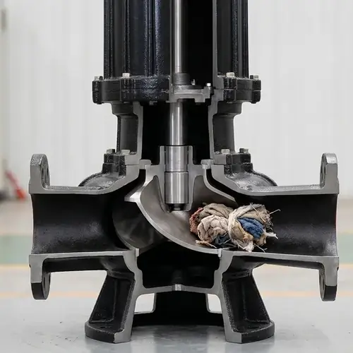
An industrial sewage pump is a solids-handling centrifugal pump specifically engineered for wastewater streams carrying rags, fibers, food waste, fibrous solids, or mineral grit—not just dirty water. You don't pick one by flow and head alone. The right pump depends on where it sits in the treatment process, what solids and concentrations it will actually see, how often it will run, and whether your maintenance crew can access it when it eventually fouls. This guide walks you through the pump architectures, impeller designs, materials, controls, and failure modes that matter when you're specifying for influent, sludge, effluent, or recirculation duty. That way you avoid the expensive mistake of buying a "general-purpose sewage pump" that rips itself apart in industrial service.
I've seen plants specify too small a solids passage, then pay for it in weekly pull-and-clean cycles. I've seen perfectly good vortex pumps fail because nobody checked the chloride content in the sludge. And I've watched buyers overpay for grinder pumps when a properly sized channel impeller pump would have handled the same waste stream with less maintenance. This page gives you the framework to make these trade-offs before you send an RFQ, not after the first breakdown.
What Is an Industrial Sewage Pump?
An industrial sewage pump moves raw or partially treated wastewater containing suspended solids, fibrous material, and sludge across treatment stages—influent lift, primary sludge transfer, return activated sludge, effluent discharge. The defining requirement is solids passage capability. While an effluent pump might handle 10–15 mm semi-solids in screened greywater, an industrial sewage pump may be specified for 50–80 mm spherical solids, and in some raw influent stations 100 mm or more, depending on the impeller geometry and test methodology used by the manufacturer. These spherical-solids ratings are standardized reference values from controlled testing, not guarantees against fibrous ragging or wipe accumulation in actual wastewater conditions.
These pumps are not interchangeable with sump pumps (intended for relatively clean water with incidental solids), grinder pumps (which macerate solids for small-diameter force mains), or positive-displacement sludge pumps (which handle thickened slurry at lower flow rates). The terminology trips people up all the time in procurement, so let's lock it down.
Sewage Pump vs Effluent Pump vs Grinder Pump
| Pump Type | Maximum Solids Passage | Typical Application | Pipe / Discharge Size | Maintenance Complexity | Best Use Case |
|---|---|---|---|---|---|
| Industrial Sewage Pump | 50–100 mm spherical solids | Raw influent, primary sludge, RAS, lift stations | 80–300 mm flanged discharge | Moderate to High — requires periodic pull-out and inspection | Un-screened municipal and industrial wastewater with rags, fibers, grit |
| Effluent Pump | 10–20 mm semi-solids | Filtered greywater, treated effluent, light commercial waste | 50–80 mm threaded or flanged | Low to Moderate | Secondary effluent discharge, septic tank effluent, small-scale dosing |
| Grinder Pump | Macerated slurry (no intact solids above 2–3 mm) | Individual building lift stations, pressure sewer systems | 32–50 mm force main | High — cutter mechanism requires regular inspection and sharpening | Locations where small-diameter piping is mandatory and flow volume is low |
| Sump Pump | 6–10 mm incidental debris | Groundwater dewatering, stormwater, basement sumps | 32–80 mm, often vertical discharge | Low | Clean or screened water with minimal solids risk |
Two points worth underlining: First, an effluent pump is not a sewage pump. If your stream contains wipes, long fibers, or rags, the 10–20 mm passage will choke in hours. Second, grinder pumps solve a hydraulic constraint (small force main pipe) but introduce a mechanical wear part that requires scheduled intervention. Don't spec a grinder pump unless your pipe size truly demands it.
How Industrial Sewage Pumps Work
Most industrial sewage pumps are single-stage centrifugal machines with an overhung impeller mounted directly to a motor shaft (in submersible designs) or extended shaft coupled to a motor (in dry-pit installations). The impeller rotates inside a volute casing, converting velocity into pressure and throwing the liquid—along with any suspended solids—into the discharge.
The difference from a clean-water pump is the impeller geometry and volute passage width. Solids must pass through the impeller eye or around the impeller perimeter without snagging. In a channel impeller design, the liquid and solids flow through a single or double large passage. In a vortex impeller, the impeller sits recessed in the volute wall, creating a rotating fluid field that sweeps most solids around the impeller periphery, reducing contact. That's why vortex pumps often tolerate rags and fibrous materials better—but they usually sacrifice hydraulic efficiency. Depending on pump size, speed, wastewater characteristics, and the supplier's hydraulic design, manufacturer testing commonly shows vortex designs operating in roughly the 35–55% efficiency range, while channel impellers may reach 65–78% at the published duty point. These are indicative ranges only. Verify the supplier's certified pump curve and test methodology for your application—typically aligned with Hydraulic Institute guidance and ISO 9906 performance testing practices—because catalog efficiencies do not guarantee identical performance in full-scale wastewater service.
Main Components and Their Failure Risks
Every industrial sewage pump has a handful of parts where failure brings the station down. Knowing what kills them changes what you ask for in procurement.
- Impeller: Channel impellers handle the largest solids but can still clog if the passage is undersized for the actual rag size. Vortex impellers sacrifice efficiency and are sensitive to improper wet-well submergence. Failure mode: erosion from abrasive grit, cracking from cavitation when NPSH is too low, or complete blockage when a tightly balled rag jams the passage. Ask the supplier for the impeller type, material grade, and minimum solids spherical diameter, not just "non-clog."
- Mechanical Seal: The seal keeps wastewater out of the motor housing. In submersible pumps, the seal chamber often sits in direct contact with the pumped liquid, so any grease leakage or seal flush failure can cause immediate damage. Common seal faces in industrial sewage: silicon carbide / silicon carbide (SiC) for abrasion resistance, or tungsten carbide for high-grit environments. Failure mode: dry-running when the pump operates against a closed discharge or under a low suction condition, which can destroy the seal faces quickly. Verify the seal specification and ask whether the seal includes a moisture probe in the oil chamber.
- Bearings: Upper and lower bearings support the shaft; in submersible pumps, the lower bearing often runs in an oil bath. Failure mode: water ingress past the mechanical seal contaminates the oil and can damage the bearings. Request bearing L10 life data for the actual duty point, not just a catalog value.
- Motor: Submersible motors (typically squirrel-cage induction) are cooled by the surrounding liquid. If the pump is sized incorrectly and runs at minimum flow for long periods, overheating and insulation breakdown can follow. Motor IP rating (IP68 is typical) matters, but what you really need to confirm is the Class H insulation rating and the service factor at full load. Overlook this, and repeated thermal cycling can significantly shorten motor life.
- Guide Rail System: In a wet-well installation, the pump slides down twin guide rails onto a base elbow with a self-sealing discharge connection. The rail-to-base alignment must be precise; if the base elbow shifts during installation, the pump won't seat properly and discharge will leak back into the wet well. During commissioning, watch for proper seating and an immediate discharge pressure spike.
- Check Valve and Isolation Valve: The discharge check valve prevents backflow when the pump stops, avoiding reverse rotation and hammer. A missing or stuck-open check valve can cause pump damage over time. Spec a resilient-seated check valve suitable for suspended solids, and pair it with a gate valve for isolation during pull-out.
Industrial Sewage Pump Types and Best Applications
Choosing a pump type means balancing solids-handling ability against efficiency, maintenance access, and footprint. Here's the field, honestly assessed.
Submersible Sewage Pumps
A submersible sewage pump is a sealed motor-and-pump unit that operates submerged in a wet well. It mounts on a guide rail system and auto-couples to a base elbow—no alignment required after pull-out. This is the default choice for municipal lift stations, industrial wastewater sumps, and any application where you want the pump out of sight and sound.
The upside: compact footprint, no exposed rotating shaft, no suction piping, and rapid installation. The downside: maintenance requires lifting the pump out of the well, and if the wet well is deep or filled with hazardous gases, that pull-out becomes a confined-space event with all the safety protocol that entails. For very large pumps above 100 kW, a dry-pit design often makes more sense simply because pulling a multi-ton submersible unit on rails is a risky operation. For deeper technical selection guidance, see our submersible sewage pump selection guide.
Dry Pit and Pedestal Pumps
In a dry-pit installation, the pump and motor sit in a dry underground or surface-level chamber, fed by a suction pipe from the wet well. The pump is coupled to a horizontal or vertical motor, and the mechanical seal is accessible without pulling the unit out of the wastewater. This design excels where you need frequent inspection, in large-capacity influent stations, or where hazardous-access rules make wet-well entry prohibitive.
The trade-off: larger footprint, more complex suction piping, and a requirement for NPSH margin calculation—which means you must account for suction pipe losses and the wet-well low-water elevation. A dry-pit pump with insufficient NPSH will cavitate and eat impellers. Always request the supplier's NPSHR curve and compare it to your calculated NPSHA with a 0.5–1.0-meter safety margin.
Vortex Impeller Pumps
A vortex impeller (also called recessed impeller) lives in a volute pocket offset from the main flow path. The impeller turns, creates a fluid vortex, and the solids move through the pump largely without touching the impeller. That's why vortex pumps handle rags, flexible wipes, and stringy materials better than almost any other centrifugal design.
The price: hydraulic efficiency is usually lower than a comparable channel-impeller design. On many submersible sewage pump curves, a vortex impeller may test in the high 30s to mid 40s percent range, while a single-channel impeller under the same duty conditions could reach the high 60s. Actual performance depends on pump geometry, solids loading, speed, and how the supplier conducted hydraulic testing. Over long operating periods, that efficiency gap can translate into higher energy consumption and a larger motor requirement. Use vortex pumps where the waste stream has unreliable screening or where you know the rag load is severe, and confirm the lifecycle energy trade-off using the supplier's tested performance curve.
Channel Impeller Non-Clog Pumps
A single-channel, two-channel, or multi-channel impeller has large curved passages sized to pass the specified solids sphere. These pumps achieve the highest efficiency of all solids-handling centrifugal designs. The passage surfaces must be hydraulically smooth (investment-cast stainless steel is common) to prevent rag accumulation. Failure mode: a "rag ball" that compacts gradually at the impeller eye or volute tongue, eventually stalling the motor. Specifying an impeller cleaning port on the volute casing gives operators a way to remove clogs without a full pull-out.
Grinder Pumps
A grinder pump has a cutting mechanism—usually a rotating cutter blade against a stationary plate—at the suction inlet that shreds solids into a fine slurry before they enter the impeller. This lets you pump through a 50 mm force main when a 100 mm gravity sewer would otherwise be required. That's the genuine use case: small-diameter pressurized sewer networks, often in hilly or remote locations.
The downside is twofold. First, the cutter is a wear part; in an industrial setting with grit or hard debris, the blades dull and require replacement. Second, grinder pumps have lower flow capacity and high head capability, so they are poorly suited to large-volume influent stations. Do not specify a grinder pump to "prevent clogs" in a standard lift station—a properly sized channel pump with adequate solids passage will do the job with far less lifetime cost.
Positive Displacement Pumps for Sludge
As a general threshold, centrifugal pumps may begin to lose efficiency when sludge reaches roughly 4–6% total solids by weight, but the exact point depends heavily on sludge rheology, pump speed, and hydraulic design. Before committing to a pump family, obtain a performance test at your actual concentration and viscosity conditions. Positive displacement (PD) pumps—progressing cavity, rotary lobe, or double-disc—are often the rational choice at higher solids concentrations. They move a fixed volume per revolution, largely independent of discharge pressure, and handle very viscous, abrasive sludge without the shear sensitivity issues that affect centrifuges downstream.
However, PD pumps cannot run dry, are sensitive to oversized solids (a metallic bolt can destroy a rotor and stator in seconds), and require pressure protection via integral relief valves or rupture discs. Procurement of a PD pump for sludge should always include a factory performance test at the actual viscosity and solids concentration, not at water. And you must plan for stator replacement as a routine maintenance item; if maintenance staff are not familiar with PD pump rebuilds, factor in outside contractor costs.
Matching Pump Types to Wastewater Process Stages
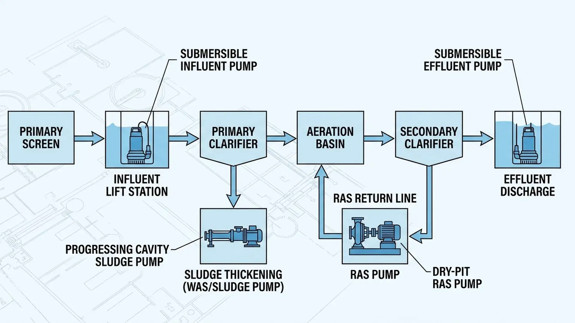
This is where many procurement specs go wrong: someone picks a pump type in isolation, without considering where it fits in the treatment chain. Each stage places different demands on the pump. Here's a practical map.
| Process Stage | Liquid / Solids Description | Preferred Pump Type | Key Selection Criteria | Typical Failure Mode |
|---|---|---|---|---|
| Raw Influent (Headworks) | Unscreened municipal or industrial waste, rags, grit, fibers, large solids up to 100 mm | Submersible channel impeller, or dry-pit single-channel pump | Solids passage ≥ 80 mm, abrasion-resistant impeller material, guide-rail pull-out capability | Rag balling at impeller eye, grit erosion of volute cut-water |
| Primary Sludge | Concentrated settled solids, 2–5% TS, organic, occasionally stringy | Submersible vortex pump, or progressing cavity PD pump if sludge is thick | Impeller resistance to rag and hair, high-chrome wear parts, slow speed to reduce wear | Seal failure from sludge packing, clogging in volute if solids content is high |
| Secondary Sludge / Waste Activated Sludge (WAS) | Light fluffy solids, 0.5–1.5% TS, tends to entrain air | Submersible or dry-pit non-clog pump, often with VFD for variable RAS rates | NPSH margin adequate for air-entrained liquid, gentle shear to avoid floc damage | Cavitation at low submergence, instability at low VFD speed |
| Return Activated Sludge (RAS) | Returned mixed liquor, low head, high flow | Vertical dry-pit axial or mixed-flow pump, or horizontal double-suction pump | High efficiency at low head, large flow capacity, ability to handle some solids in suspension | Entrained air causing vibration, biological growth in volute reducing efficiency |
| Final Effluent | Treated, clarified water with minimal suspended solids | Submersible or dry-pit centrifugal pump, sometimes multistage for high head | Solids passage 10–15 mm sufficient, stainless steel casing if chlorides are present | Minimal if properly sized; watch for corrosion from residual disinfectants |
| Scum / Grease Pumping | Floating grease, scum, mixed with water and occasional solids | Vortex impeller submersible pump, or diaphragm pump | Materials resistant to low pH if grease is acidic, non-clog volute, wide solids passage | Grease solidification inside volute if pump sits idle for long periods |
After you match the pump type to the process stage, the next layer of precision comes from wet-well geometry and lift station design. For a full technical walkthrough of sizing, redundancy, and control logic, read our wastewater lift station pump sizing guide.
How to Reduce Clogging, Ragging, and Downtime
Clogging is rarely caused by a single oversize solid. It's usually a system problem: a pump that's too big for the actual flow running at low speed, a wet well that encourages vortex formation and pre-rags the fibers, or a screen that lets through a steady stream of flushable wipes.
Here's what you check before blaming the pump:
- Pump sizing at the average daily flow, not only peak flow. An oversized pump cycles on and off too fast, then runs at a throttled condition where the impeller doesn't sweep the volute properly—a common condition for rag accumulation. Right-size the pump to the duty point where it will run most hours, then verify that the peak design flow can be handled by a second (standby) pump in parallel.
- Wet well floor geometry. If the sump floor slopes toward the pump suction with a 45° or steeper fillet, solids slide toward the pump naturally. Flat-bottomed sumps with corners accumulate solids that break loose in clumps and jam the impeller. Ask for a well profile that meets the pump manufacturer's sump design recommendations.
- Low-flow continuous operation with a VFD. Variable frequency drives save energy, but sewage pumps often have a minimum practical operating speed below which solids may begin settling inside the volute. The acceptable lower limit is not universal; it depends on impeller geometry, solids characteristics, pump size, and the manufacturer's hydraulic validation testing. Some suppliers discourage extended operation below roughly 30–35 Hz on certain solids-handling designs, while others publish different validated ranges. If your duty range requires deep turndown, request documented operating limits and confirm the approved speed range with the supplier for the exact pump and wastewater conditions.
- Screening efficiency at the headworks. If wipes, rags, and stringy material pass the 25 mm bar screen in large quantities, no pump impeller—channel or vortex—will stay clog-free indefinitely. You either upgrade the screen or accept a higher pull-out frequency and budget for it. Pretending the pump alone will solve a screening problem is a recurring source of maintenance pain.
For a much deeper dive into root causes and prevention strategies, wastewater pump clogging prevention strategies lays out the full risk assessment, including impeller-specific anti-ragging features and the economic trade-offs.
Materials, Controls, and Installation Considerations
What a pump is made of and how it's controlled determines whether it survives the first five years or becomes a permanent budget line item for replacement. Industrial wastewater is chemically aggressive—varying pH, dissolved chlorides from process or disinfectant sources, and hydrogen sulfide at the wet-well headspace creating acidic condensation. Standard cast iron (ASTM A48 Class 30 or EN-GJL-200) is commonly used in municipal sewage, but long-term corrosion resistance depends on factors such as pH, temperature, aeration, chloride concentration, and actual wastewater composition. The material guidance below is directional rather than universal; confirm compatibility through supplier corrosion review, site chemistry data, and project-specific material recommendations.
| Component | Material Option | Typical Specification Grade | Best For | Risk / Verification |
|---|---|---|---|---|
| Volute and Casing | Cast iron | EN-GJL-200 or equivalent | Municipal sewage and many general wastewater duties | Corrosion resistance varies with pH, temperature, aeration, sulfides, and chloride loading. Review actual wastewater chemistry with the supplier and consider coupon testing where conditions are uncertain. |
| 304 Stainless Steel | 1.4301 | Food-grade or mild chemical waste | Chloride-related pitting risk increases in some high-chloride or elevated-temperature services; confirm suitability with the supplier's corrosion data. | |
| 316 Stainless Steel | 1.4401 | Industrial effluent, coastal locations, moderate chlorides | Improved chloride resistance versus 304, but actual performance still depends on chemistry and temperature. Verify molybdenum content and request material certification. | |
| Duplex Stainless Steel | 1.4462 | High salinity, brine, aggressive chemical waste | Higher cost; confirm actual PREN (Pitting Resistance Equivalent Number) > 35 from supplier. | |
| Impeller | Cast iron + high-chrome insert | Cr 26–28% | Abrasive raw sewage with grit | High-chrome wear ring must be integrally cast, not pressed; ask for cross-section photo. |
| 316 Stainless Steel | 1.4401 | Industrial effluent with corrosion risk | Hydraulically smooth investment-cast surfaces required to prevent rag build-up. | |
| Shaft | 431 Stainless Steel | AISI 431 | General submersible duty | Tapered shaft end preferable for impeller retention; confirm keyless connection type. |
| Mechanical Seal Faces | SiC / SiC | – | Most municipal and light industrial sewage | Sensitive to thermal shock; confirm seal design includes carbon vs SiC stationary seat. |
| Tungsten Carbide / Tungsten Carbide | – | High grit, abrasive sludge | Higher running temperature; check motor insulation class accordingly. | |
| Guide Rails | 304 Stainless Steel | – | Wet well installation | Rails must be continuous and sized to support pump weight plus snag load; confirm zinc-plated steel is not acceptable. |
| Exterior Coating | Two-part epoxy | ≥ 250 μm DFT | Submerged service | Must pass pinhole inspection; ask for coating application record. |
Beyond materials, the control system defines operational reliability. Level control should use a redundant float or ultrasonic signal—never a single-point switch. VFD panels should include an anti-jam cycle (momentary reverse or bump forward) for submersible pumps prone to rag build-up, and SCADA integration should provide real-time motor current and vibration trending so that operators see a developing clog as a rising amp curve days before a trip. On the mechanical side, install an inline check valve with an external lever and counterweight so the flapper can be exercised manually, and include a full-port gate valve for each pump to enable single-pump isolation during service.
Industrial Sewage Pump RFQ Checklist
Sending a technically complete RFQ prevents the supplier from guessing your duty, and that guess is usually wrong and expensive. Supply these data points up front.
| RFQ Data Field | Your Input / Options (to confirm with site data) |
|---|---|
| Pumped liquid description | Raw sewage / primary sludge / activated sludge / effluent / scum |
| Maximum solids size and type | Spherical size (mm), description (rags, fibers, grit, grease) |
| Design flow rate | m³/h or L/s at duty point |
| Total dynamic head (TDH) | meters, with static head and friction losses separated |
| Available NPSH | meters, calculated at minimum wet-well level |
| Maximum operating temperature | °C |
| pH range and chemical composition | pH min/max, chloride concentration (mg/L), presence of oils/solvents |
| Power supply | Voltage, phase, frequency |
| Installation type | Submersible wet-well / dry-pit horizontal / vertical pedestal |
| Duty cycle | Continuous or intermittent, hours per day |
| Required standby pump | Yes/No, and required parallel capacity |
| VFD requirement | If yes, speed range (Hz) |
| Explosion-proof motor required | If yes, ATEX/IECEx zone classification |
| Discharge connection standard | Flanged standard (EN 1092, ANSI B16.5) and size |
| Guide rail system | Required or not, rail length and material |
| Control and monitoring | Float/ultrasonic, SCADA signal (4–20 mA, Modbus), moisture probe |
| Documentation requested | Pump performance curve, material certificates, mechanical seal drawing, motor data sheet, factory test report |
| Inspection | Standard / witnessed test, ISO 9906 grade |
| Packaging | Export sea-freight containerization, anti-corrosion protection |
| Spare parts | Recommended startup spares (seal kit, gaskets, wear ring) |
Once you've completed the RFQ, apply the industrial pump selection framework to check whether your hydraulic selection is consistent with the system curve, duty cycle, and lifecycle cost.
FAQ
Buyers consistently ask these technical questions when narrowing down industrial sewage pump options. I've answered them the way I would in a design review meeting—directly and with the trade-offs.
What solids size can an industrial sewage pump handle?
Most industrial sewage pumps are specified to pass a sphere of 50 mm, 65 mm, 80 mm, or 100 mm depending on the impeller design. A channel impeller pump rated for 80 mm solids passage can reliably move an 80 mm diameter ball or soft solid of equivalent consistency, but a long, stringy rag that measures 80 mm in a ball shape may still wrap around the impeller hub. The solids passage number from the manufacturer is a spherical diameter under clean-water test conditions, not a guarantee that all fibrous materials of that diameter will pass. For rag-heavy waste, specify the intended rag load explicitly and ask the supplier to confirm past performance in similar installations.
When is a grinder pump necessary?
A grinder pump is necessary when your discharge piping diameter is too small to pass the expected solids size—for example, a pressurized sewer system using 50 mm HDPE force mains where gravity sewers are not feasible. It is not a universal clog-prevention tool. For a standard lift station with 100–150 mm discharge piping, specifying a grinder pump adds an unnecessary wear component and reduces pumping capacity without solving the root cause of clogging.
Are vortex impellers better than channel impellers?
Neither is categorically better. Vortex impellers resist rag-related clogging more effectively because solids rarely contact the impeller directly, but they often operate in the 35–55% hydraulic efficiency range. Channel impellers typically reach 65–78% efficiency and are usually the better choice when the waste stream is reasonably well-screened or the solids load is dominated by grit and organic matter rather than wipes and rags. If your plant has minimal headworks screening and you're pulling pumps weekly, a vortex impeller may cut that to monthly pull-outs—and the energy penalty becomes a secondary cost. Always confirm the expected efficiency using the supplier's performance curve for your specific duty point and installed motor.
What pump is used for activated sludge?
For return activated sludge (RAS) at typical mixed-liquor suspended solids concentrations, large submersible single-channel pumps or vertical dry-pit non-clog pumps are common. The challenge is air entrainment from the aeration basin, which reduces NPSH availability and can cause cavitation. For waste activated sludge (WAS) with high air content and low solids, a slow-speed submersible pump with VFD speed control can maintain stable flow without hydraulic instability. Avoid high-speed, small-passage pumps—they tend to lose prime or vibrate when ingesting aerated liquid.
How often should sewage pumps be inspected?
A common engineering baseline for submersible sewage pumps in continuous municipal duty is to pull and inspect every 6 to 12 months, but the actual interval should be adjusted based on the manufacturer's maintenance manual, condition monitoring data (vibration, motor current, seal moisture alarms), and site-specific grit loading or operational history. Inspection should include impeller clearance measurement, seal oil analysis (if applicable), bearing noise check, and cable insulation resistance test. If the pump is pulling high moisture probe alarms or showing rising motor current trends, pull it immediately—waiting until a failure is a false economy when the standby pump then runs solo while the failed unit sits for weeks awaiting repair. The preventive maintenance plan for industrial pumps provides a full schedule for daily through annual checks.
Conclusion
The best industrial sewage pump for your plant is not the one with the most impressive catalog claims about clog resistance. It's the one where the impeller type matches the actual solids in your waste stream, the material grade accounts for your chloride and pH levels, and the installation layout lets your maintenance crew pull and service it without a crane and a two-day safety permit. Start with the process stage—influent, sludge, effluent—then narrow the pump family, then verify the solids passage, material, seal, and control details against the worst-case operating condition, not just the design point. Send an RFQ that includes all those data fields, and require the pump curve, material certs, and test records before you accept a delivery date. This discipline doesn't guarantee zero downtime, but it eliminates the self-inflicted failures that sour operations teams on new equipment.
Get A Quote

Get A Quote
0 Comments