
End Suction Pump Selection Guide: Flow, Layout, NPSH, and Maintenance
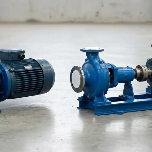
An end suction pump is a single-stage centrifugal pump where the suction inlet sits horizontally on the end of the casing, in line with the shaft, and the discharge outlet rises vertically from the top — at 90 degrees to the suction line. You select it correctly by matching your actual flow and head to the pump's best efficiency point, confirming the system's NPSHa exceeds the pump's NPSHr with a practical safety margin, choosing close-coupled or frame-mounted layout, piping the suction side without air traps, and specifying a back pull-out design so your maintenance crew isn't stuck disconnecting pipe for a seal change.
The real cost of getting this wrong is not just the price of a new impeller. It's vibration, cavitation pitting, repeated mechanical seal failures, energy waste from a pump that never runs near its best efficiency point, and a mechanical room that's difficult to maintain. This guide walks you through each decision in the order a buyer actually makes it — hydraulic range and standards, NPSH, layout, piping, maintenance access — so you can send a technically complete RFQ instead of a vague list of flow and head.
Start from the required duty point, not the catalog headline. If you confirm the five items in the Quick Answer below, you'll have already eliminated most of the expensive selection errors I see in international pump sourcing.
Quick Answer / 30-Second Buyer Decision
As a planning reference, a typical end suction pump envelope for clean-water industrial duty is roughly 5–5,000 GPM at 15–650 ft of head; some large-frame heavy-duty models may approach 9,000 GPM. These are not universal limits — model curves must be checked at the actual duty point. Above roughly 650 ft, you should usually be comparing multistage pumps instead. Within that practical envelope, the five checks that matter before you quote anything are:
- Operate near BEP: keep the duty point inside about 70–120% of the pump's best efficiency point as a planning guide, not a hard cutoff.
- Verify suction energy: NPSHa must exceed NPSHr by roughly 3–5 ft — and those two numbers are not the same.
- Choose the layout: close-coupled saves space and skips alignment; frame-mounted handles heat, power, and maintenance better.
- Pipe the suction correctly: eccentric reducer flat side up, 5–10 pipe diameters of straight run, zero pipe strain on the casing.
- Specify maintenance access: back pull-out design with a spacer coupling cuts seal and bearing repair time.
If any of those five doesn't ring true for your system, keep reading before you write the RFQ. If they all match, jump to the RFQ checklist and send a complete package.
Scope of This Guide
This page covers standalone selection of industrial end suction pumps for clean water, process water, cooling, utility, and light chemical transfer duty. That includes operating limits, dimensional standards (ANSI B73.1 and ISO 2858), NPSH selection logic, mounting layout, suction piping rules, seal choices, and the maintenance economics of a back pull-out build.
It does not cover a full deep dive into multistage or inline pump mechanics, residential water systems, slurry or solids-heavy sewage pumping, or detailed seal flush plan engineering. Those are separate topics — I keep the cross-references brief so this page stays focused on the selection decision in front of you.
I wrote this for engineering project managers, mechanical contractors, wholesale buyers, OEM procurement leads, and maintenance engineers who already know they need a centrifugal pump and are shortlisting between configurations and suppliers before issuing an RFQ.
What Is an End Suction Pump? (Operating Limits & Standards)
The standard end suction pump — also called an end suction centrifugal pump — is a horizontal, single-stage, overhung impeller design. The suction flange is on the end of the casing, axially aligned with the shaft. The discharge flange is on top, perpendicular to the shaft. That one geometry is why the pump is so common: the top discharge helps air and vapor vent during normal operation, it fits on a simple baseplate, and it's straightforward to inspect. That does not make the pump self-priming, and normal priming requirements still apply.
The overhung impeller means the impeller sits on the free end of the shaft, supported by bearings on one side only. There's no second bearing on the suction side. That's what makes the back pull-out arrangement possible — the whole rotor can slide out from behind without opening the casing.
Functionally, the horizontal-end suction and top discharge create a compact flow path. The liquid enters the eye of the impeller axially, the impeller pushes it outward through a volute, and it leaves from the top. Casing and impeller are the two main wetted parts; a mechanical seal isolates the shaft; bearing frame and motor drive it.
For a reference build, the electric single-stage end-suction centrifugal pump page shows a common single-stage configuration in practice.
Operating Limits: Where the Envelope Actually Ends
For clean-water process duty, a standard process water pump envelope is commonly planned around 5–5,000 GPM at 15–650 ft of head, but treat that as a planning reference, not a category-wide guarantee. Some large-frame heavy-duty models may approach 9,000 GPM; that is the upper edge, not the comfortable middle. Actual capability must be confirmed on the specific model curve at the quoted duty point.
The lower bound is largely a practicality issue. Below roughly 5 GPM, you're usually better served by a small close-coupled, a vertical multistage, or a different pump type because the end suction casing and mechanical seal overhead don't pay back.
The upper head bound matters more. A single-stage overhung impeller hits diminishing returns somewhere around the 650 ft mark for water. Above that, you're forcing high impeller tip speeds and casing pressure for one stage — a multistage pump is almost always the more rational choice. Don't spec a single-stage end suction pump at 900 ft of head just because the catalog shows one line diagram. Get the multistage comparison instead.
ANSI B73.1 vs. ISO 2858: Dimensions Are Not Performance
A common sourcing mistake is treating a dimensional standard like a performance guarantee. ANSI/ASME B73.1 and ISO 2858 both define physical configurations for horizontal end suction process pumps — flange positions, mounting dimensions, overall envelope — so buyers can swap one manufacturer's pump for another without re-piping. They are not hydraulic specifications.
ANSI B73.1 grew out of the US chemical process industry. It defines both dimensions and a set of design requirements for horizontal end suction process pumps, including centerline discharge, sealed design, back pull-out construction, and provisions for shaft sealing. A pump built to ANSI dimensions is supposed to be dimensionally interchangeable with another ANSI pump of the same size, but NPSHr, efficiency, materials, and wear ring clearances will still differ between manufacturers.
ISO 2858 is the metric counterpart, designating end suction pump dimensions with a 16 bar rating series. The technical design and performance requirements sit in ISO 5199, not ISO 2858. ISO 2858 dimensional interchangeability applies within its own defined size and duty-point series, not across the entire practical end suction pump market envelope. So a pump can be dimensionally ISO 2858 but not ISO 5199-compliant — confirm which one your specification actually names.
| Standard | Region of Origin | Primary Focus | Dimensional Interchangeability | Pressure Rating |
|---|---|---|---|---|
| ANSI/ASME B73.1 | North America / US chemical process | Horizontal end suction process pump design and interchangeability | Yes — within ANSI size class, allowing manufacturer swaps | Defined by flange class and casing design; confirm per model |
| ISO 2858 | Europe / metric markets | End suction pump nominal duty points and dimensions | Yes — within ISO size number | 16 bar rating series is the base reference; confirm actual |
| ISO 5199 (supporting spec) | International | Technical design, materials, and testing requirements for Class II pumps | No — supplements dimensional standards | Not a rating by itself; governs technical quality |
So when a supplier says "ISO pump," the first question back is: ISO 2858 dimensions, ISO 5199 design, or both? That distinction alone separates a quoting shop from a technical supplier.
Energy compliance is a separate layer. In the US, DOE 10 CFR 431 sets a Pump Energy Index (PEI) benchmark of 1.00 for a defined clean-water pump scope that often falls within the 1–200 HP band, but not every pump in that power range is automatically covered. Confirm the regulatory category and scope for the exact model and destination. When buying for the US market, ask whether the quoted model meets the applicable PEI threshold rather than assuming all efficiency-labeled pumps do. Outside the regulated scope, still ask for the actual efficiency at your duty point, not the peak catalog number.
Hydraulic Selection: Matching Flow, Head, and NPSH
Three hydraulic variables decide whether an end suction pump works in the field: Total Dynamic Head, the efficiency position around Best Efficiency Point, and the NPSH margin at the impeller eye. They are connected — flow sets TDH, TDH sets the operating point on the curve, and NPSH tells you whether the pump can accept the suction conditions at that operating point. Work through them in that order, and the rest of the selection is mostly layout and commercial verification.
Total Dynamic Head and the System Curve
Pump buyers often fixate on maximum flow and maximum head as if they happened at the same time. They don't. Total Dynamic Head (TDH) is the sum of static lift, friction losses, and any required system pressure at a given flow. As flow through a closed system increases, friction rises — so the required head rises too. The pump doesn't decide the operating point by itself; it operates where its performance curve intersects the system curve.
That's why the first piece of selection work is the duty point, not "a 200 GPM pump." You need minimum, normal, and maximum flow, and the TDH at each. Max flow often has the highest TDH; minimum flow can create its own recirculation problem if the pump is oversized.
If you need to work through the TDH and NPSH math step by step before choosing a model, the industrial pump selection guide walks through the calculation with examples.
Best Efficiency Point (BEP): The Financial Sweet Spot
Every pump curve has a Best Efficiency Point — the flow/head pair where hydraulic and mechanical efficiency peak. Pumps don't live there naturally; the system curve determines where they run. Your job is to match the duty point close to BEP.
A working band of roughly 70–120% of BEP flow is the zone I typically tell buyers to hold as a planning guide, not a hard cutoff. Inside it, the pump usually runs quieter, seals stay cooler, and energy use is more predictable. Outside it — especially well left of BEP or far right of the curve — you get suction and discharge recirculation, higher vibration, shorter seal and bearing life, and more energy per gallon.
The classic mistake is oversizing. Somebody adds a generous safety factor, then the actual process runs well left of BEP for years. That's not a safe design; it's a quietly expensive one. If you need modest future capacity, you can sometimes specify the motor for max flow while trimming the impeller so normal operation lands near BEP. If the future flow or head increase is materially higher, select the pump casing and hydraulic size for the future duty from the start, or define a planned impeller trim/VFD strategy with the supplier. Better yet, consider a VFD and verify the pump can handle the turndown without hitting NPSH limits at speed.
NPSH: The Two Numbers That Must Not Meet
Cavitation is one of the most preventable failure modes in an end suction pump, and almost every cavitation story starts with someone confusing NPSHa and NPSHr.
- NPSHa (available): a property of your system — how much absolute pressure head remains above the liquid's vapor pressure at the impeller eye. It depends on suction source height, fluid temperature, vapor pressure, altitude, and suction piping losses. You calculate it. The manufacturer cannot know your NPSHa.
- NPSHr (required): a property of the pump — how much NPSH the pump needs at that flow. It's read off the pump's NPSHr curve and rises as flow pushes toward the right end of the performance curve. The manufacturer provides it from testing.
The selection rule is blunt: NPSHa must exceed NPSHr by a margin. For standard clean-water duty near BEP, a 3–5 ft margin is a planning rule of thumb, not a universal safety factor. Hot water, fluids near their vapor point, high-suction-energy conditions, hydrocarbon service, or operation far right of BEP may need more. Ask your engineer or supplier for the margin appropriate to your fluid.
Here's the catch most buyers miss: NPSHr rises near the end of the curve. A pump that has plenty of NPSH margin at normal flow can cavitate at maximum flow because NPSHr climbed while NPSHa dropped from increased friction in the suction line. When you check NPSH, check it at maximum flow, not at normal duty.
Suction lift makes this visible. At sea level, water offers roughly 34 ft of barometric head. Subtract vapor pressure, NPSHr, suction line friction, and your safety margin, and the practical lift is far less than the theoretical number. At altitude or in hot water, the margin shrinks further. That's why a "max suction lift" number on a datasheet isn't the same as your on-site capability. Do the calculation.
So before you send an RFQ, write down your calculated NPSHa. Not a guess — the number. If you can't produce it, say so and ask the supplier to help with a suction analysis, but do not let them silently skip the check.
Installation Layout: Close-Coupled vs. Frame-Mounted
The same hydraulic duty can be built two physically different ways. The choice affects installation space, alignment work, heat transfer, and how painful maintenance is later.
Close-Coupled (Monobloc)
In a close-coupled design, the pump casing mounts directly to the motor flange and the motor shaft doubles as the pump shaft, or a stub shaft carries the impeller. There is no separate bearing frame and no coupling to align. That cuts parts, footprint, and commissioning time.
The trade-offs: motor bearings take the hydraulic thrust and radial loads. Heat from the liquid conducts into the motor. If the motor or the shaft seal fails, lifting the whole unit is often the repair path. Close-coupled suits moderate clean-water duty — HVAC, booster service, small transfer — where temperatures are low, the fluid is non-corrosive, and the unit can be unbolted and swapped quickly.
Frame-Mounted (Long-Coupled)
A frame-mounted pump has its own shaft, supported by dedicated bearings in a bearing frame. A flexible coupling connects the pump shaft to a separate motor, both on a shared baseplate. You get a more serviceable rotor, better load isolation for the motor, and the ability to handle higher power and temperature. The baseplate gets grouted to concrete, and after the grout cures, the shaft alignment is set with a laser and rechecked after piping is attached — soft foot included.
This configuration costs more and needs more floor space. In a heavy industrial or process environment, that's usually a good trade because the downtime math dominates. A close-coupled pump in a 24/7 process line may save floor space and cost you hours in repair when the motor or seal fails.
| Feature | Close-Coupled | Frame-Mounted |
|---|---|---|
| Shaft and bearings | Motor bearings carry pump loads | Dedicated pump bearing frame |
| Alignment | No coupling alignment needed | Laser alignment after grouting; recheck after piping |
| Footprint | Compact | Larger, baseplate + motor |
| Heat transfer | Liquid heat reaches motor | Less direct heat path to motor |
| Serviceability | Often lift the whole unit | Pull the rotor assembly via back pull-out |
| Practical use | Clean water, HVAC, small boosters, tight rooms | Process water, chemical transfer, higher power, high temperature |
The decision rule I give buyers is simple: if downtime is expensive and the duty is tough, choose frame-mounted and spend the extra money on grout and alignment. If you're moving clean ambient water in a mechanical room where a swap is fast, close-coupled is a legitimate, cheaper choice.
Suction Piping Best Practices to Prevent Pump Failure
Piping mistakes rarely show up on opening day. They show up as seal failures months later, vibration reports, or a pump that never delivers rated flow. The suction side is where most of the sins happen because air, turbulence, and pipe strain don't announce themselves until the seals and bearings start paying.
Eccentric Reducer, Flat Side Up
Do not put a concentric reducer on a horizontal suction line to an end suction pump. A concentric reducer creates a high spot where air collects, and that air pocket chokes the suction and damages the seal. Use an eccentric reducer instead, installed with the flat side up so the top edge stays straight and no air pocket can form. If the liquid source is above and the line drops down into the pump, confirm orientation with your engineer; for the standard horizontal clean-water case, flat side up is the rule.
Straight Run and Pipe Size
Give the pump 5–10 pipe diameters of straight pipe before the suction flange. That lets flow straighten before the impeller eye. An elbow immediately before the suction flange throws non-uniform flow into the eye, which can cause vibration and local cavitation even when your calculated NPSHa looks fine.
Keep the suction pipe at least as large as the pump suction nozzle. Larger suction pipe is generally fine; smaller is not acceptable for a clean-water end suction pump.
Casing Strain and Support
Suction and discharge piping must be supported independently of the pump. The pump casing is a pressure vessel, not a pipe hanger. When installers bolt up piping without adequate supports and then force flanges into alignment, the casing distorts. You get shaft misalignment, seal face contact problems, and bearing vibration. Support the pipe, align flanges without force, and make sure the pipe weight isn't hanging on the casing.
Slope, Valves, and Air
For suction lift installations, slope horizontal suction lines slightly up toward the pump so air migrates toward the pump and out through the discharge. For flooded suction from an elevated source, slope the horizontal run downward toward the pump or route it with no high points so vapor cannot collect. The correct slope direction follows the suction source location — it is not a single universal rule. Install full-bore isolation valves on the suction and discharge so you can isolate the pump for maintenance without draining the whole system. If you use a temporary suction strainer during commissioning, monitor its differential pressure — a clogged strainer is a man-made NPSHa problem.
| Suction Piping Rule | Why It Matters | Buyer Action |
|---|---|---|
| Eccentric reducer, flat side up | Prevents air pocket formation in horizontal suction lines | Specify in installation drawing |
| 5–10 diameters of straight run | Reduces turbulence and uneven flow into the impeller eye | Confirm available run before RFQ |
| Suction pipe ≥ nozzle size | Avoids restricting available suction head | Check pipe schedule in project |
| Independent pipe supports | Prevents casing strain and shaft misalignment | Include in installer scope |
| Slope direction follows suction source: up toward pump for suction lift; downward toward pump or no high points for flooded suction | Prevents air pocket formation in both suction-lift and flooded-suction layouts | Confirm suction source location and specify slope direction in installation drawing |
| Full-bore isolation valves | Makes pump service possible without system drain | Specify valve type and size |
Here's the mental model: every suction-side mistake either reduces NPSHa, introduces air, or strains the rotating assembly. If your calculated NPSHa is borderline, the suction pipe is usually the first place to look.
Maintenance Economics: The Back Pull-Out Advantage
When I look at a pump quote, I ask one question before the price: can this pump be repaired without cutting the piping? If the answer is no, the invoice price is hiding a future labor bill.
The back pull-out pump design is the break that makes end suction pumps maintainable. The casing stays bolted to the suction and discharge piping and to the foundation. The rotating assembly — impeller, shaft, bearing frame, mechanical seal, and seal chamber — is designed to slide out backward as one assembled rotating section. A spacer coupling makes this cleaner: you remove the spacer element, so the motor and pump shafts don't need to be moved far, and then pull the rotor assembly without disconnecting the casing or disturbing alignment.
What does that save in practice? A seal change stops being a piping job. The maintenance crew unbolts the bearing frame, pulls the rotor assembly, replaces the seal on the bench, and slides it back. The piping stays hot, lined up, and drained-free. On a frame-mounted end suction pump, that usually means the seal repair happens on the bench, with the piping left alone. On a pump that must be lifted out or have spools cut, the same job can eat far more labor and downtime.
Seal choice is the other half of the maintenance equation. For clean water, a standard carbon/ceramic or silicon carbide seal is common. For process water with solids, heat, or aggressive chemistry, specify the seal faces, elastomers, and flush plan — SiC/SiC faces with the right elastomer and a clean flush line generally run longer than a low-cost standard seal. Seal dry running is a fast killer: do not run an end suction pump dry. Cavitation failure is different — it typically attacks impeller vane and casing surfaces first as material pitting, while mechanical seal life usually suffers indirectly through vibration, pressure pulsation, or loss of seal flush to the seal chamber.
If you want to stretch seal life on the pump you already have, the practical actions that extend mechanical seal life are worth reviewing before you write the next service contract.
The RFQ lesson is concrete: write "back pull-out design with spacer coupling" as a hard requirement, not a nice-to-have. Suppliers who only offer a standard close-coupled pump may still sell you a good pump, but they're selling you a different maintenance future. Buy the future you want.
Supplier Verification: What to Check Before You Pay the Deposit
The selection is only as good as the factory evidence behind it. Here's what I ask for before committing volume to a pump manufacturer, and what you should ask for too. Scale the documentation and witness requirements to the pump size, project risk, and service severity: full MTR packages, witnessed ISO 9906 testing, and detailed balance documentation are common on larger or critical-process pumps, but they can add cost and lead time on small clean-water utility pumps.
Hydraulic test curve to ISO 9906. Ask for the test certificate at the quoted duty point, not the brochure curve. ISO 9906 defines the test grades; confirm which grade the supplier uses and whether the test is witnessed or factory standard. Witnessed testing is more common for larger, higher-risk, or contract-critical pumps and may not be necessary for every small clean-water package unit. Also confirm the test was performed at rated speed with the quoted impeller, not a bench curve that happens to look close. A pump that meets flow but misses head or efficiency by a few points is not the same pump you specified.
Viscosity-corrected performance curve. If the fluid viscosity is materially above water, water-duty curves can give the wrong operating picture. Request corrected performance curves at the quoted duty point instead of relying on uncorrected catalog data.
Material test reports. For casing, impeller, shaft, wear rings, and seal components, get MTRs against the named material standard where the project risk, fluid service, or compliance scope justifies traceability. Cast iron, 316 stainless, and duplex stainless may all require documented traceability if the fluid is aggressive or the specification calls for it.
Dimensional interchangeability documentation. Verify suction and discharge flange positions, bolt patterns, and mounting dimensions against ANSI B73.1 or ISO 2858 as applicable. Request a dimensional drawing with nozzle coordinates and flange drilling. A dimensionally non-compliant pump creates re-piping costs.
Impeller dynamic balance report. Overhung impellers benefit from dynamic balancing. Request the balance report or the balance grade for the specific impeller and speed where vibration risk, pump size, or project requirements justify it; smaller, lower-speed impellers may not require the same documentation level or balance procedure as large high-speed units.
Casing pressure test. Confirm hydrostatic/pressure test of the casing and a report. The test pressure should be stated and signed off.
Coupling and alignment record. For frame-mounted units, ask for the coupling type and whether the factory pre-aligns on the baseplate. You'll still re-align after installation, but a factory check catches gross errors.
Motor documentation. Nameplate photo or data sheet: voltage, phase, frequency, IP rating, insulation class, and motor efficiency class relevant to the destination market.
Packaging and transport bracing. For sea freight, heavy frame-mounted pumps need export-grade wooden crates with the motor braced and the shaft locked to prevent bearing brinelling in transit. Ask for packing photos before the shipment leaves — not after a claim is filed.
All of these are buyer-verifiable, not trust-me statements. If a supplier hesitates on any of them for a serious industrial order, wait until they produce the document.
RFQ Checklist: How to Specify an Industrial End Suction Pump
Send the list below with your inquiry and the supplier can return a meaningful quotation on the first pass. Fill in every line that applies — leaving a blank pushes the supplier to assume, and assumptions create change orders. If your liquid viscosity is materially above water, request viscosity-corrected performance curves instead of water-duty curves. Also require a dimensional drawing showing nozzle coordinates and flange drilling to verify any ANSI/ISO claim before you commit.
| Field | What to Provide / Options |
|---|---|
| Liquid type | Clean water, process water, cooling water, light chemical, other |
| Liquid temperature | Min / normal / max |
| Specific gravity / viscosity | Value, or "water at ambient" |
| Viscosity correction | Confirm if viscosity is materially above water; request corrected performance curves |
| Solids / abrasives | None, trace, or specify size and concentration |
| Required flow | Min / normal / max, in GPM or m³/h |
| Total Dynamic Head | Min / normal / max, in ft or m |
| NPSHa at pump suction | Your calculated value at max flow |
| Suction pressure | If not atmospheric |
| Site elevation / ambient temp | For NPSH margin and motor derating |
| Power supply | Voltage, phase, frequency |
| Motor requirements | IP rating, insulation class, efficiency class, hazardous area if any |
| Preferred materials | Casing, impeller, shaft, wear ring, seal faces |
| Mechanical seal | Single/cartridge, seal face material, elastomer, flush plan |
| Dimensional standard | ANSI B73.1 or ISO 2858 |
| Layout | Close-coupled or frame-mounted; back pull-out with spacer coupling if required |
| Customization / OEM | Data plate, paint specification, private label branding, accessory list |
| Testing | ISO 9906 grade, witnessed test option |
| Documentation | MTRs, balance report, pressure test, dimensional drawing with nozzle coordinates and flange drilling |
| Packaging | Export wooden crate, motor bracing, shaft lock |
| Quantity and target date | For MOQ and lead time check |
Once you've filled this out, you're no longer asking "can you quote a pump?" — you're asking a supplier to answer a specific engineering question. That changes the conversation and the quote quality.
Common Mistakes That Turn a Good End Suction Pump Into a Bad Investment
Every one of these is avoidable in the specification stage:
- Oversizing the pump so it runs well left of BEP, wasting energy and shaking.
- Ignoring NPSHa at maximum flow because it was fine at normal flow.
- Using a concentric reducer on the suction line and blaming the seal for failing.
- Hanging pipe weight on the casing during installation, then chasing vibration forever.
- Specifying "ANSI pump" or "ISO pump" without knowing whether that's a dimensional or technical requirement.
- Buying on first cost only, with no back pull-out or spacer coupling, then paying for hours of maintenance labor on every seal change.
- Accepting a brochure curve instead of a certified ISO 9906 test curve at the duty point.
- Not asking for packaging details until the pump arrives with a cracked baseplate or corrosion from transit moisture.
If you correct even half of these before the order, you'll separate yourself from most projects that end up with "pump problems" that were actually specification problems.
FAQ: End Suction Pump Selection Questions Answered
These are the short, practical answers to questions I get repeatedly from engineers and procurement teams before they finalize an end suction pump order.
What is the maximum flow of an end suction pump?
For standard single-stage industrial models, expect roughly 5–5,000 GPM for most catalog selections, with some heavy-duty end suction centrifugal pumps reaching toward 9,000 GPM. Above that, double-suction split-case pumps usually become the better choice. Confirm the specific model's curve at your required flow rather than assuming a "large flow" catalog number matches your duty point.
What is the difference between close-coupled and frame-mounted end suction pumps?
Close-coupled (monobloc) pumps mount the casing directly to the motor, often sharing the shaft, with no coupling to align. They're compact and cheaper but transfer liquid heat to the motor and are harder to service in heavy duty. Frame-mounted pumps have a dedicated bearing frame and a flexible coupling between pump and motor on a shared baseplate. They handle higher power and temperature better and offer back pull-out serviceability, but they cost more and need proper grouting and laser alignment.
How do you pipe an end suction pump?
Keep the suction pipe at least as large as the pump suction nozzle, give it 5–10 pipe diameters of straight run before the suction flange, use an eccentric reducer with the flat side up on horizontal runs, support all piping independently of the pump casing, and slope the horizontal suction line according to the suction source: up toward the pump for suction lift, or downward toward the pump with no high points for flooded suction. Avoid concentric reducers, short-radius elbows right before the flange, and forcing flanges into alignment.
Why is the discharge on top of an end suction pump?
The top discharge helps air and vapor move out of the volute during normal operation instead of collecting against the impeller, which reduces the chance of air binding. It does not make the pump self-priming, and the suction line still has to be properly filled and vented during startup. The arrangement also puts the discharge pipe above the casing, simplifying standard horizontal piping layouts and keeping the suction line separate from the discharge.
Can an end suction pump run dry?
No. The mechanical seal depends on the pumped liquid for lubrication and cooling, and the impeller/casing clearances are not designed for dry operation. Even a brief dry run can damage the seal faces. Suction loss, a closed suction valve, or a vapor lock can all cause dry running, so include low-flow or dry-run protection in the controls if your process can lose prime.
When should I use an inline pump instead of an end suction pump?
Choose an inline pump when the mechanical room is severely space-constrained and your flow and head requirements are moderate. Inline pumps align the suction and discharge along the same pipe axis, which can simplify piping, but they generally offer less maintenance access and more limited large-flow capacity. For a fuller trade-off, review the comparison of end suction, inline, and multistage pumps before locking the category.
Official Sources and Compliance References
These standards anchor the selection logic above and are the references your project engineer or compliance team may already be using:
- ANSI/ASME B73.1 — Horizontal end suction centrifugal pumps for chemical process service. Use it to define dimensional interchangeability and process design requirements for US-market projects.
- ISO 2858 — End suction centrifugal pumps (rating 16 bar), designation, nominal duty point, and dimensions. Use it for metric-dimensional interchangeability.
- ISO 5199 — Technical specifications for centrifugal pumps, Class II. Use it to define design, materials, and testing quality requirements beyond the dimensional format.
- ISO 9906 — Hydraulic performance test grades for rotodynamic pumps. Use it to request a certified test curve at your duty point, including the grade name in the RFQ.
- DOE 10 CFR 431 (US) — Pump Energy Index benchmark for clean water pumps within the regulated power band. Use it to check US-market energy compliance; confirm the model's PEI and regulatory category with the supplier rather than assuming universal compliance.
Where any standard version, scope, or test grade is material to your project, confirm the exact edition and scope with the manufacturer and with the project specification before you sign the PO.
Conclusion
An end suction pump earns its place as the industrial workhorse when four things are true: the duty point sits in the 5–5,000 GPM / 15–650 ft practical planning envelope, the system provides enough NPSHa margin at maximum flow, the suction piping follows the flat-side-up eccentric reducer rules and the slope direction matched to the suction source, and the pump itself is a back pull-out frame that your maintenance crew can service with the piping in place.
Run those four checks first. Then choose close-coupled or frame-mounted from the real space and downtime constraints, ask for the ISO 9906 test curve at your duty point, and send the RFQ table with every field filled. That sequence protects you from the two costs that seldom show up on the invoice: wasted energy and wasted maintenance hours.
When you're ready to compare a concrete build against your data sheet, start with Liqen's end suction pump product range and confirm the configuration, standard, and documentation requirements match your specification.
Get A Quote

Get A Quote
0 Comments