
Boiler Feed Pump Selection: Why Multistage Pumps Are Used in High-Pressure Steam
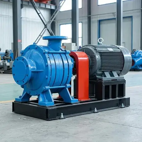
A boiler feed pump does one job that sounds simple but punishes mistakes hard: it pushes feedwater from the deaerator into a steam boiler against that boiler’s own operating pressure — continuously, at high temperature, with zero room for vapor bubbles that can eat an impeller. In any steam system running above about 15–20 bar, a single-stage centrifugal pump simply cannot deliver enough head efficiently and stably. That’s why industrial boiler feed applications typically rely on multistage centrifugal pumps, which build pressure stage by stage across multiple impellers in series. Get the selection wrong and you don’t just lose efficiency — you risk cavitation damage, thrust bearing failures, seal blowouts, and unplanned boiler shutdowns that cost far more than the pump itself.
This guide is written for project engineers and procurement teams who need to size, specify, and verify a boiler feed pump for high-pressure steam service. It doesn’t rehash generic multistage theory. Instead, it walks you through the real pressure-staging logic, the NPSH trap that hot deaerated water springs on you, axial thrust management you need to confirm with the supplier, material choices that match your water chemistry, and exactly what belongs in your RFQ so you don’t get a pump that “looks right” but fails at 2 a.m. six months later. If you’re already reviewing bids or preparing a datasheet, you’ll find the verification checklist and common mistakes section worth a close look.
Once you understand the core risks, the next step is straightforward: calculate the true discharge head requirement, specify continuous-duty materials, lock in a solid NPSH margin above the pump’s NPSHr at duty temperature, and insist on a factory-tested performance curve before shipment. Let’s get into the details.
Quick Answer: What a Boiler Feed Pump Actually Does
A boiler feed pump takes treated, deaerated water — usually around 102–105°C straight from a deaerator storage tank — and forces it into the boiler drum at a pressure higher than the boiler’s maximum operating pressure. Under ASME Section I rules, the feed pump discharge pressure must exceed the highest safety valve setting by at least 3%. That means if your boiler safety valves are set at 65 bar, your pump needs to deliver at least 67 bar at the drum inlet, plus whatever you lose in piping, check valves, control valves, and elevation rise. This is not a circulation pump circulating already-heated water inside a loop; it’s a feed pump pushing liquid against a pressure barrier, and the margin matters. Miss the margin by even a few percent, and the boiler can starve, triggering a low-water trip that takes the whole steam system offline.
Scope of This Guide
We’ll focus on horizontal multistage ring-section and barrel-type centrifugal pumps for boiler feed service in industrial and small-to-medium power stations — what you’d specify for boilers from roughly 20 bar up to ~120 bar, though many principles scale higher. We’ll touch on API 610 when relevant, but we won’t wander into large utility turbine-driven feed pump trains that involve complex lube-oil skids and full API 610 OH2/BB5 arrangements with separate gearboxes. We also won’t cover boiler water chemistry in depth or low-pressure HVAC circulators. This is squarely aimed at the engineer or buyer who already knows they have a steam boiler and needs to get the feed pump right.
Why Multistage Pumps Are Used for Boiler Feed Applications
A centrifugal impeller can only develop so much head in a single stage before running into stability and efficiency limits. For clean hot water at boiler feed temperatures (say 105°C, specific gravity ~0.96), a single-stage impeller might reach roughly 100–150 meters of head before you need an impeller diameter so large that NPSH requirements climb and efficiency drops. Your boiler likely demands 600, 900, or 1,200 meters of head. That’s where a multistage pump earns its place: each impeller and diffuser set adds a manageable pressure increment, and the rotor string can be built with as many stages as needed — 6, 8, 12, even 16 stages — to hit the total head while keeping each stage near its best efficiency point (BEP).
What matters more is that multistage pumps let you stay in a higher efficiency band. A properly selected 8-stage pump can typically achieve hydraulic efficiency in the 75–78% range, while a single-stage pump forced to work at the same extreme head may fall below 60% in many cases and would consume substantially more power. Over the pump’s working life, that efficiency gap alone can cost you more in extra electricity than the purchase price, sometimes several times over.
Single-Stage vs Multistage Boiler Feed Pumps
The trade-off isn’t just head. The table below lays out the differences a buyer should compare.
| Criterion | Single-Stage Feed Pump | Multistage Feed Pump |
|---|---|---|
| Max practical head (hot water) | ~150–200 m | 600–1,500+ m, stage-dependent |
| Efficiency at high head | Drops sharply above ~120 m | Holds 72–80% across wide head range |
| NPSHr at duty point | Often higher for same flow | Can be lower per-stage, but total NPSHr still matters |
| Axial thrust | Moderate, simple bearing | High, requires balancing device (disc or drum) |
| Maintenance complexity | Lower — fewer wear parts, less teardown time | Higher — more stages, more wear rings, more seals to inspect |
| Capital cost for low-head service | Lower | Higher, but only sensible when head demands it |
| Lifecycle cost in high-head service | Higher (poor efficiency, frequent impeller replacement) | Lower when operated within BEP envelope |
| Continuous-duty reliability | Good up to moderate pressure | Better at sustained high pressure with correct thrust balance |
A common question from buyers is whether a cheap single-stage pump can be “pushed” to meet boiler duty through higher impeller trim or motor overspeed. In most industrial boiler feed applications, that approach creates trade-offs in efficiency, stability, and bearing life. You’ll often end up operating far right on a steep curve, NPSHr will spike, and bearing loads will shorten life significantly. Once required head moves beyond roughly 200 meters, multistage designs are typically preferred — and in many cases effectively required — depending on flow, efficiency targets, and overall operating conditions.
How Boiler Feed Pump Pressure Is Calculated
This is where even experienced specifiers make costly assumptions. The required pump discharge pressure is not just the boiler’s operating pressure. You must sum:
- Boiler drum pressure at maximum steam load (or safety valve set pressure, whichever is higher)
- ASME-mandated margin (3% minimum above safety valve setting)
- Static elevation difference between the pump centerline and the feedwater nozzle entrance at the drum
- Friction losses in the feedwater line from pump discharge to boiler inlet (suction piping losses are handled separately in NPSHa)
- Pressure drop across the feedwater control valve and any check valve, typically in the 3–5 bar range for a modulating valve but confirm with the valve data sheet
- A small contingency for future tube fouling — a few percent, often 2–5%, depending on confirmed water treatment quality
Example: a boiler with safety valves at 65 bar, 15-meter static lift from pump to drum, 3 bar friction loss, 4 bar control valve drop, and 3% ASME margin (≈ 2 bar). The pump discharge head requirement becomes roughly 65 + 2 + (15 m × 0.096 bar/m ≈ 1.4 bar) + 3 + 4 = ~75.4 bar, plus contingency. That’s about 785 meters of head at 105°C. A single stage won’t touch it. A well-chosen 9-stage pump might, assuming each stage delivers about 87 meters comfortably.
Many RFQs we see specify only “pump discharge pressure XX bar” without the breakdown. A supplier who doesn’t ask for the missing pieces is guessing. A good one sends back a TDH calculation and asks you to confirm. Before you submit your RFQ, read our guide on multistage pump selection for high-head water supply — it covers the data suppliers actually need to avoid a mismatch.
Cavitation Control and NPSH in Boiler Feed Systems
Cavitation kills boiler feed pumps faster than any other failure mode. Hot deaerator water sits dangerously close to its vapor pressure. At 105°C, the vapor pressure of water is about 1.2 bar absolute. If the suction pressure at the pump inlet drops anywhere near that, the water flashes into steam bubbles inside the impeller eye, and those bubbles collapse violently against the metal, chewing it away like sandblasting run by a jackhammer.
NPSH Available (NPSHa) is what your system provides; NPSH Required (NPSHr) is what the pump manufacturer’s curve says the pump needs at a given flow to avoid more than 3% head drop (the standard definition). For boiler feed, meeting NPSHa > NPSHr is not enough; a margin is required. As a common guideline, specify a margin of at least 1 meter, and often 1.5–2 meters for services with wide load swings, but always confirm the required margin against the specific pump’s NPSHr curve and the Hydraulic Institute’s recommendations for hot water (ANSI/HI 9.6.1). What trips up most specifiers is the deaerator elevation. The deaerator must be mounted high enough above the pump so that the static head provides sufficient NPSHa when you subtract suction piping losses and the liquid vapor pressure head. In older plants where the deaerator is at grade and the pump is in a pit, you’re very likely to experience cavitation unless you add a booster pump — which adds complexity and an extra failure point.
Common Causes of Boiler Feed Pump Cavitation
- Deaerator tank level too low — If the storage tank level drops during high demand, the static head shrinks and NPSHa collapses.
- Suction pipe too small — Undersized suction lines increase fluid velocity and friction loss, lowering inlet pressure.
- Strainer blockage — A partially plugged suction strainer creates a pressure drop you don’t see until the pump starts rattling.
- Excessive water temperature — Deaerator pressure-control failure can let water temperature spike above design, raising vapor pressure.
- Pump operated far right of BEP — At higher flows, NPSHr rises sharply on many pump curves, and if your system head curve drops off, you can slide into cavitation without realizing.
- Air ingress at flanges or pump shaft seal — Even a tiny air leak on the suction side reduces effective NPSHa because of two-phase flow.
For a full checklist that includes NPSH verification, refer to our centrifugal pump buying checklist — it includes specific NPSH margin verification steps you should use during technical bid evaluation.
Axial Thrust Management in Multistage Boiler Feed Pumps
Stick six, eight, or twelve impellers on a single shaft, and each one generates a hydraulic axial force trying to shove the shaft toward the suction end. If you don’t neutralize that thrust, the thrust bearing gets overloaded and fails — sometimes catastrophically. This is not a minor detail; it’s a design feature you must confirm with the supplier.
In ring-section multistage pumps (the most common type for industrial boiler feed up to about 100 bar), axial thrust is typically balanced by a balance drum and balance disc arrangement behind the last impeller. The balance device uses pump discharge pressure on one side and lower pressure on the back side to create a counter-force that pushes the rotor toward the discharge end. A small amount of controlled leakage through the balance device runs back to the pump suction or a flash tank. If that balance device wears — and it does — the thrust bearing sees higher load, leading to axial rotor movement and rubbing of wear rings.
When evaluating suppliers, ask these three things: - What type of axial thrust balancing does this model use (balance drum, disc, opposed impeller layout)? - What is the design thrust bearing life at rated conditions? - How is wear in the balance device monitored — axial position indicator, vibration, or periodic disassembly?
Cheaper pumps may omit proper balancing and rely solely on thrust bearings on both ends, which might work for a fire pump that runs a few hours a month but not for a pump that runs 24/7, day in, day out.
Material Selection for Hot Boiler Feedwater
Hot, deaerated, chemically treated water sounds friendly, but it can still corrode low-alloy cast iron or standard carbon steel over time if pH drifts or oxygen pitting occurs. For most industrial boiler feed pumps (up to ~120°C, pH ~8.5–9.5), the typical material spec is:
- Casing and diffusers: Cast carbon steel (WCB) or ductile iron for moderate pressures; barrel-type pumps for higher pressures often use forged or cast alloy steel.
- Impellers: 12% chrome stainless steel (CA-15 or equivalent) for erosion and corrosion resistance; duplex stainless can be specified for borderline water chemistry.
- Shaft: 410 stainless steel or 4140 steel with appropriate corrosion allowance, often hard-chrome-plated under mechanical seal areas.
- Wear rings: Bronze or 400-series stainless, replaceable at both casing and impeller. Confirm with the supplier that wear ring clearances match the expected operating temperature so they don’t gall during warm-up.
- Mechanical seal: Faces in carbon vs. silicon carbide are standard for hot water; many boiler feed pumps use a balanced single seal with an API Plan 23 flush (recirculation from pump discharge through a cooler) to keep the seal chamber below 80°C. Plan 23 is critical — it directly taps filtered discharge water, cools it, and forces cooled water across the seal faces. Ask the supplier if the seal housing is sized for this plan.
| Material Component | Common Selection | Max Temp Suitability | Notes |
|---|---|---|---|
| Casing | Cast carbon steel (WCB) | Up to ~425°C (but fluid is ~105°C) | Good for boiler feed; check corrosion allowance |
| Impeller | 12% Cr stainless steel (CA-15) | ~120°C (fluid temp) | Resists erosion; avoid if chlorides >100 ppm |
| Shaft | 410 SS or 4140 | ~150°C | Hard-coat under seal faces |
| Wear rings | 416 SS or bronze | ~120°C | Replaceable; verify clearance for thermal expansion |
| Mechanical seal faces | Carbon / Silicon Carbide | Seal chamber <80°C | Plan 23 flush recommended |
| Diffusers | Ductile iron / carbon steel | ~120°C | Match casing material grade |
If your water has residual oxygen above 7 ppb or fluctuating pH, a duplex stainless impeller might be worth the extra cost — but confirm water analysis data first. Don’t guess.
How to Specify a Boiler Feed Pump for RFQ
An incomplete specification generates proposals that look different but are really just different guesses. Here’s what you give a supplier so you get back comparable, accurate selections.
| Specification Field | Your Required Data or Options |
|---|---|
| Flow rate | Normal and rated m³/h, with any swing range (e.g., 40–60 m³/h) |
| Total dynamic head | Specified at rated flow, accounting for boiler pressure, static lift, pipe losses, control valve, margin |
| NPSHa at pump suction flange | At rated flow, minimum deaerator level, and maximum water temperature |
| Liquid | Boiler feedwater after deaerator; specific gravity ~0.96 at 105°C |
| Water temperature range | Normal / max (e.g., 102°C normal, 110°C max) |
| pH and dissolved oxygen | Treated water quality data if available |
| Boiler operating pressure | Maximum design pressure and safety valve set pressure |
| Pump type preference | Horizontal ring-section multistage unless pressure dictates barrel |
| Motor | kW, voltage, phase, frequency, enclosure (IP55 minimum), insulation class F or H |
| Continuous or intermittent duty | 24/7 year-round vs. seasonal or backup |
| Standards | ISO 9906 Grade 2 (or Grade 1) for hydraulic testing; API 610 if specified |
| Required documents | Data sheet, certified performance curve (with NPSHr), GA drawing, motor data sheet, material certificates |
| Testing | Hydrostatic test, performance test, dynamic balance of rotor |
| Factory witness test | Yes/No — specify if you or your third-party inspector will attend |
| Seaworthy packaging | Export crate with corrosion protection |
Suppliers who push back and ask for more detail (especially NPSHa, actual boiler pressure, or control valve characteristics) are usually the ones worth keeping on the shortlist. The ones who just fill in their standard boiler feed pump datasheet without questions are often cutting corners you’ll find later.
Supplier Verification and Factory Testing
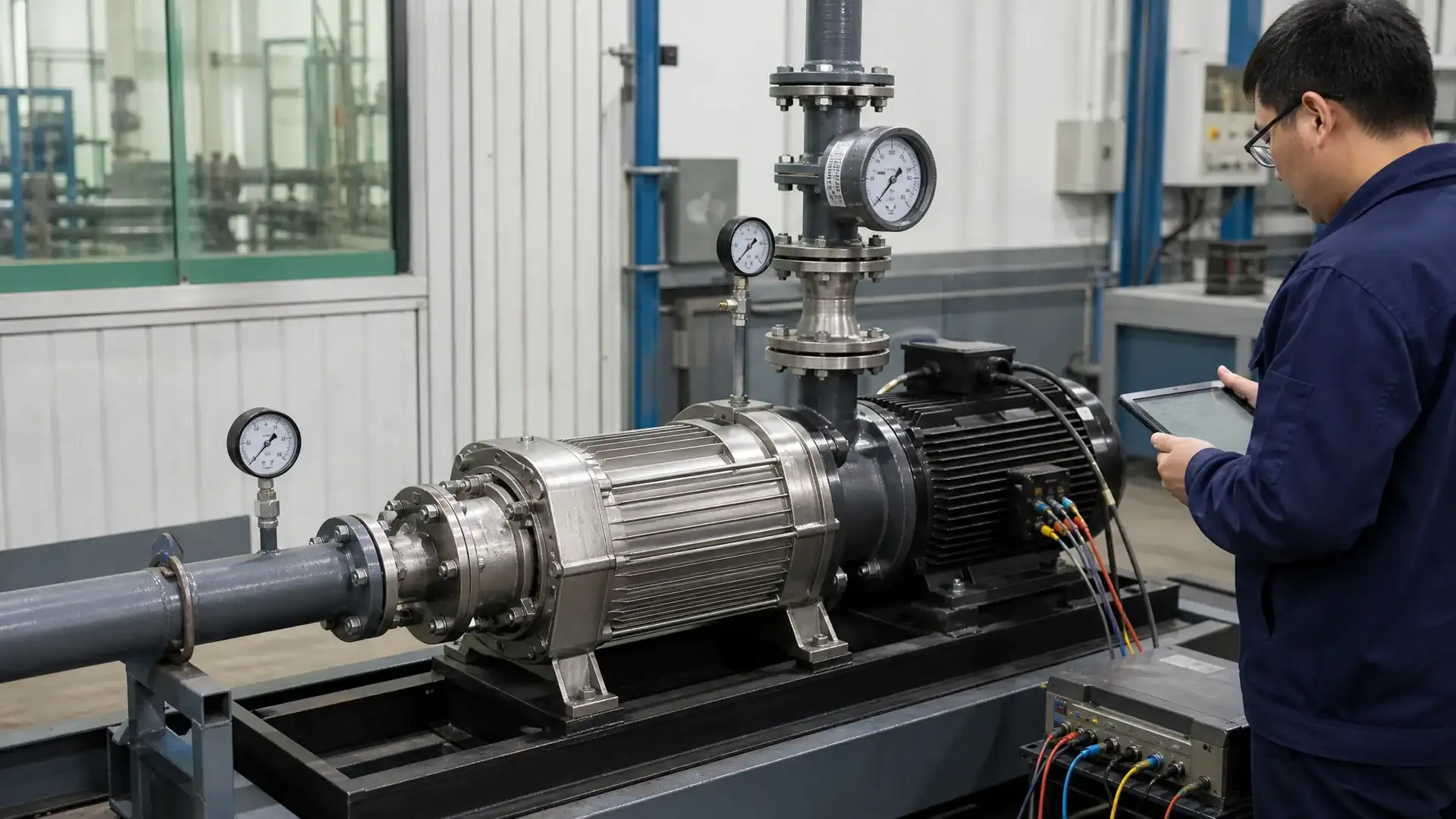
After you receive quotes, verify before you commit. Before shipment, the pump curve, material certificates, and test reports are the primary objective documents buyers can use to confirm that the offered pump matches the specified duty and construction requirements.
Certified Performance Curve Request an ISO 9906 Grade 2 (or Grade 1) witnessed curve showing head, power, efficiency, and NPSHr across the full flow range, with the rated point marked. Compare the supplied head at your rated flow with your calculated requirement — including the ASME margin. Do not accept a catalogue curve stamped “typical.” It must be specific to the impeller trim and stage count offered.
Hydrostatic Pressure Test The casing should be hydro-tested to 1.5 times the maximum allowable working pressure, documented with time and test pressure hold time. Get a copy of the test report.
Dynamic Balance of Rotor Ask for a rotor balance report that complies with ISO 21940 Grade 2.5 or equivalent. A continuous-duty multistage pump with an unbalanced rotor vibrates from day one.
Material Certificates 3.1 certificates per EN 10204 for castings, impellers, and shaft are a minimum. For safety-critical service, some buyers demand 3.2 certificates with third-party inspection sign-off.
Witness Testing If your boiler is high-value or your contract requires it, you can attend the factory test. A typical witness test package includes performance curve verification (witnessed), NPSHr test (if agreed), hydrostatic test, and mechanical running test. Request a firm quotation for the witness-test cost, as it often adds a significant percentage to the pump price depending on project scope and test complexity. The extra spend buys you a confirmed pump before it gets wrapped in pallet film.
For projects where this pump is just one of several in a power plant, also review boiler feed and condensate pump selection for power plants — that article helps you coordinate pump specifications across all of the plant’s water and steam systems.
FAQ — Boiler Feed Pump Selection Questions
Here are the questions that come up most often when sizing feed pumps or troubleshooting field issues.
Can a boiler feed pump use a VFD?
Yes, and in many multi-boiler plants, a VFD (variable frequency drive) on the feed pump improves part-load efficiency and reduces control valve erosion because you can throttle feedwater flow by changing pump speed instead of closing a control valve against full pressure. However, you must coordinate with the boiler controls: if steam demand drops suddenly, the VFD must follow the level controller signal without delay. Ensure the motor and pump are rated for the entire speed range, and confirm that the pump’s minimum continuous stable flow (typically 20–30% of BEP) is above the churn flow at lowest speed. Also, at lower speeds, NPSHr reduces, which is helpful, but don’t rely on that to fix a poor suction layout.
What is the difference between a deaerator feed pump and a boiler feed pump?
In many smaller systems, these are the same pump — it takes water from the deaerator and pushes it into the boiler. In larger systems, you sometimes see a dedicated “deaerator feed pump” that simply transfers water from the condensate receiver to the deaerator, while a separate high-pressure boiler feed pump sends deaerated water into the boiler. The deaerator feed pump handles lower pressure and lower temperature (often 80–90°C), while the boiler feed pump handles the high head and saturated water near 105°C. From a procurement standpoint, specify based on the actual suction source and discharge pressure requirement, not the name.
When should buyers request API 610 compliance?
API 610 (ISO 13709) becomes necessary when the boiler feed pump is in refinery, petrochemical, or high-criticality service where downtime carries safety or major revenue loss risk. In conventional industrial plants or biomass power boilers, a well-built non-API multistage pump can serve reliably for decades. API 610 adds specific design requirements — barrel casing, heavier bearing housings, particular seal chamber dimensions, shaft stiffness limits — that can often increase cost significantly; in many cases, it can double the price of a robust industrial-grade pump, though the exact premium depends on configuration. Request it if your project specification demands it or if the boiler is part of an oil/gas process unit. Otherwise, specify robust industrial-grade construction with proper balancing and material selection, and focus your verification effort on testing and documentation. Always request a firm quotation for an accurate cost comparison.
How much NPSH margin is recommended?
As a common starting point, specify a minimum 1-meter margin between NPSHa and NPSHr at rated flow and maximum operating temperature, but always verify the required margin against the supplier’s NPSHr curve. If your load varies widely and the pump may operate above rated flow, a margin of 1.5–2 meters is often specified, since NPSHr typically rises at higher flows. Confirm with the supplier that NPSHr data is based on the 3% head drop criterion and not a weaker definition. Also, re-calculate NPSHa at the worst-case deaerator level and during rapid load ramps; don’t design for “normal” conditions only.
What causes premature seal failure in boiler feed pumps?
The most common killers are (1) vapor flashing in the seal chamber due to inadequate flush cooling — hot water at 105°C can vaporize across the seal faces if the seal chamber pressure drops too low; (2) dirty flush water from unfiltered discharge recirculation that erodes seal faces; (3) a seal environment not kept above the fluid vapor pressure margin, often due to a missing or undersized cooler in a Plan 23 flush circuit; and (4) shaft misalignment or rotor imbalance that causes vibration and early wear of seal faces. When a supplier offers a mechanical seal, ask for the seal chamber temperature and pressure calculations at rated flow, and confirm the flush plan is detailed in the data sheet.
Official Sources and Compliance References
Several industry standards guide boiler feed pump specification and testing. While not exhaustive, these are the most commonly referenced in industrial and small power plant procurement. Buyers should confirm the latest applicable edition, project contract requirements, and any regional or jurisdiction-specific adaptations before finalizing an RFQ or compliance review:
- ASME Boiler and Pressure Vessel Code Section I, PG-61.1: mandates feedwater supply requirements and the minimum pressure margin above safety valve setting.
- API 610 / ISO 13709: covers centrifugal pump design for petroleum, petrochemical, and natural gas industries; often referenced for heaviest-duty boiler feed pumps with barrel casings.
- ANSI/HI 9.6.1: Hydraulic Institute standard for NPSH margin recommendations based on suction specific speed and application — relevant for hot water services.
- ISO 9906: defines hydraulic performance test acceptance grades (Grade 1, 2, 3) for rotodynamic pumps; you’ll use this to specify test tolerance and measurement uncertainty in your RFQ.
When you reference these in an RFQ, specify the exact section or grade, not just “pump to be as per API 610” — that’s too vague.
For a deeper look at how to define high-pressure requirements with a supplier, check our guide on how to select a multistage pump for high-pressure water systems. It walks through the pressure calculation and pump sizing logic from a system integrator’s perspective.
Conclusion: What to Prioritize in a Boiler Feed Pump Specification
A wrong boiler feed pump selection doesn’t just waste money — it creates operational risk that compounds over time. The three priorities any project engineer should nail down are:
- Get the total discharge head right, including the ASME margin and all real system losses. Check this before accepting any bid.
- Verify NPSH margin under worst-case conditions — low deaerator level, max temperature, and max flow. Use a margin that matches the pump curve and system dynamics; relying on a fixed number without confirming against the specific NPSHr data invites risk.
- Insist on a certified performance curve, material certificates, and rotor balance report before shipment. If the supplier won’t provide these, find a different one.
Everything else — material selection, thrust balancing design, seal flush plan — follows from these three fundamentals. If you start your specification with accurate operating data and hold suppliers to documented test evidence, you’ll end up with a pump that runs reliably, year after year, without surprise downtime.
Get A Quote

Get A Quote
0 Comments