
Plunger Pump vs Centrifugal Pump: Pressure, Dosing & Transfer Selection
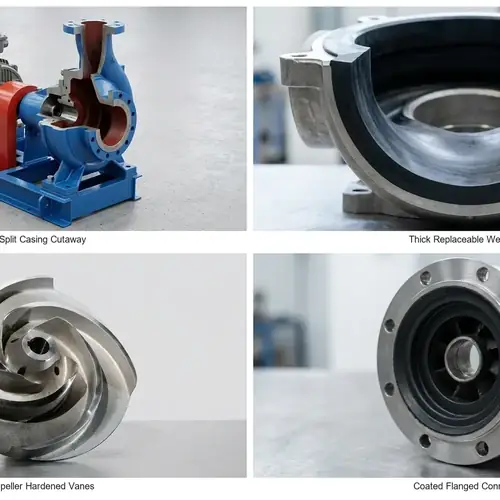
If your system needs very high pressure with controlled flow — water jetting, chemical injection, metering — a plunger pump is usually the right call. If you’re moving large volumes continuously at lower pressures, a centrifugal pump is almost always more practical and less expensive to own. The mess happens when buyers treat these two as interchangeable. They’re not. A centrifugal pump pushed into a dosing role becomes an accuracy headache. A plunger pump spec’d for bulk transfer burns through maintenance budgets and pulsation problems nobody budgeted for. That’s the real plunger pump vs centrifugal pump trade-off.
This article walks you through the real decision — technical, commercial, maintenance — so you can match the pump technology to the actual job without overspending or picking the wrong family. By the end you’ll know which pump deserves your RFQ and what verification steps to build into supplier discussions before committing to a purchase.
Quick Answer: Plunger Pump vs Centrifugal Pump — Which One to Choose?
When you first approach the plunger pump vs centrifugal pump decision, start with the pressure requirement. Below roughly 30–40 bar, most centrifugal pumps can be configured to work — single-stage, multistage, or with high-speed designs depending on flow. Above that, you start drifting into plunger pump territory fast. But pressure isn’t the only gate. Three other factors flip the decision:
- Dosing accuracy. If your process requires tight, repeatable flow control — think ±1% or better — plunger pumps, especially those built to API 675, are designed for this kind of metering. Centrifugal pumps rely on stable system resistance for steady flow, which real processes rarely guarantee.
- Fluid viscosity and solids. Centrifugal pumps lose efficiency rapidly as viscosity climbs. Plunger pumps handle viscous fluids better but struggle with abrasive solids that eat valve seats and packing.
- Pulsation tolerance. Plunger pumps produce pressure pulses. If your downstream piping, instrumentation, or process cannot accept pulsation, you either add dampeners (cost and complexity) or consider whether a multistage centrifugal can work instead.
For a quick look at how pressure and flow priorities affect selection, see high head pump vs high flow pump.
The table below gets you to a shortlist in under 30 seconds.
| Criteria | Plunger Pump | Centrifugal Pump |
|---|---|---|
| Pressure capability | High to very high (typically > 40 bar into hundreds) | Low to medium-high (single/multistage; practical limits vary by design) |
| Flow profile | Relatively constant flow despite pressure swings | Flow changes with system resistance |
| Pulsation | Inherent, requires dampener for smooth flow | Typically smooth, minor vane-pass pulsation |
| Viscosity tolerance | Good — maintains efficiency with thicker fluids | Declines above roughly 200–300 cP; needs correction |
| Solids handling | Poor — abrasive particles destroy valve seats and packing quickly | Better, especially with open-impeller or slurry designs |
| Dosing / metering accuracy | Excellent, down to ±1% or tighter with proper configuration and calibration | Poor without flow control loops and stable backpressure |
| Maintenance profile | Higher — valves, packing, seals are routine wear points | Generally lower, unless handling abrasive/corrosive fluids |
| Energy use at high pressure | Often more efficient where centrifugal would fall off BEP | Efficiency collapses if forced far left of BEP or into excessive staging |
| Typical applications | Water jetting, oilfield injection, chemical dosing, pressure washing | Water supply, HVAC, irrigation, process transfer, bulk handling |
Scope of This Guide
This comparison covers positive displacement reciprocating plunger pumps (typically triplex or quintuplex configuration) versus rotodynamic centrifugal pumps (single-stage, multistage, end-suction, split-case, vertical configurations). We touch on axial piston and diaphragm pumps only where they help clarify selection boundaries; those deserve their own separate guides. The focus is industrial procurement — you’re buying for a factory, a water treatment plant, an oilfield injection system, a pressure-washing operation, or a chemical dosing skid. Not residential, not small workshop tools.
We’ll walk through pressure logic, flow stability, solids and viscosity trade-offs, maintenance cost drivers, real industrial applications, and the RFQ data you need to send a supplier. The point is moving you from “I think I need a high-pressure pump” to “I know which technology and what verification steps apply to my job.”
How Each Pump Works — and Why It Changes System Performance
Understanding the basic mechanics isn’t about theory. It’s about predicting how your pump will behave when discharge pressure swings, when viscosity changes, or when a valve starts wearing. The two pump families generate pressure in fundamentally different ways, and that difference dictates everything downstream.
How a Plunger Pump Generates Pressure
A plunger pump is a positive displacement reciprocating machine. A crankshaft drives a connecting rod, which pushes a plunger back and forth inside a cylinder. On the suction stroke, the plunger retracts, the suction check valve opens, and fluid fills the chamber. On the discharge stroke, the plunger advances, the suction valve closes, the discharge valve opens, and fluid is physically pushed out of the pump into the system.
The critical point: each stroke displaces a mechanically determined volume of liquid. The pump doesn’t suddenly pump less just because pressure climbs, though internal leakage gradually increases with pressure. Pressure is a consequence of system resistance, not something the pump “decides.” This is why plunger pumps maintain flow far more predictably than centrifugals when downstream conditions change, and why they’re the foundation of metering and dosing applications.
The downside is pulsation. A triplex pump (three plungers operating 120 degrees out of phase) smooths the flow significantly compared to a simplex design, but the output is still a series of pressure pulses, not a continuous smooth stream. Triplex configurations can reduce pulsation amplitude to something manageable, but if your process instrumentation or piping is sensitive, you’ll still need a pulsation dampener.
The wet end typically uses one of two sealing approaches: packed stuffing boxes (more common in industrial high-pressure service, lower initial cost, requires periodic adjustment and controlled leakage) or mechanical seals (tighter leakage control but more sensitive to solids and misalignment). Plunger materials vary by service — ceramic plungers for clean-water high-pressure applications, hardened stainless steel for oilfield or chemical service, and coated options where corrosion resistance matters.
How a Centrifugal Pump Generates Flow
A centrifugal pump works on a completely different principle. An impeller rotating at high speed accelerates liquid outward from the center. The volute or diffuser converts that velocity into pressure. The key relationship: flow rate depends on the difference between pump discharge pressure and system resistance. If discharge pressure rises against a closing valve, flow drops. If system resistance falls, flow increases.
This means a centrifugal pump’s output isn’t fixed — it slides along its performance curve as conditions change. That’s fine for bulk transfer where flow rate variation of 5–10% doesn’t matter. It’s a serious problem for dosing, injection, or any process where you need repeatable, predictable delivery against variable backpressure.
The other consequence: centrifugal pump efficiency has a best efficiency point (BEP). Run the pump far to the left (high head, low flow) or far to the right (low head, high flow) of BEP and you get vibration, recirculation damage, and wasted energy. Plunger pumps don’t have this BEP sensitivity — their volumetric efficiency changes gradually with pressure and condition, but they don’t suddenly go unstable at the edge of a curve.
Pressure Capability and High-Pressure Selection Logic
The factor that most often forces the plunger pump vs centrifugal pump choice is pressure. Ask any experienced pump buyer what goes wrong with high-pressure selection, and they’ll tell you the same thing: people spec a centrifugal pump because “it’s simpler and cheaper,” then wonder why it can’t hold pressure or burns through seals. The pressure threshold where technology choice really starts to matter depends on flow rate too, but there’s a practical framework.
When Plunger Pumps Become the Safer Choice
If your duty point requires discharge pressure above roughly 40–50 bar at any flow, start your comparison with plunger pumps. Yes, multistage centrifugal pumps can reach these pressures. But as pressure climbs, the centrifugal option gets more expensive and more complex — you add stages, tighten clearances, increase NPSH requirements, and watch efficiency degrade as wear rings open up.
Plunger pumps scale pressure more directly. A triplex plunger pump with proper plunger diameter and crankshaft RPM can deliver from dozens to hundreds of bar without fundamental design changes. Applications like water jetting (commonly 400 bar and above), oilfield injection (200–350 bar), and chemical reactor feed (100–250 bar) are plunger pump territory for good reason.
For applications governed by API 674 (positive displacement reciprocating pumps for oil, gas, and chemical service), you’re going to see specific requirements for pressure testing, material traceability, and performance verification. A centrifugal pump built for the same pressure might need so much customization that the “simpler” argument disappears. Check whether your project specification references API 674 — if it does, your technology decision may already be partially made.
When Multistage Centrifugal Pumps Still Make Sense
Don’t assume high pressure always means plunger. If your flow is high — say 50 m³/h or more — and your pressure target is moderate (20–60 bar), a multistage centrifugal pump can be the more economical choice with the right configuration. Boiler feed pumps in power plants operate at 60–120 bar using centrifugal designs, and they run reliably for years. The difference is they were selected with full knowledge of the BEP, the NPSH margin, and the wear-ring maintenance schedule.
A centrifugal pump working at 40 bar might need 6–10 stages, tight internal clearances, and careful attention to suction conditions. It won’t tolerate solids, won’t meter accurately, and won’t like stopping and starting against high backpressure — but for clean, continuous high-flow service, it works. When evaluating this option, review the multistage pump selection for high-head water supply to understand where staging becomes the right answer versus switching to positive displacement technology.
The table below gives a practical — not absolute — boundary zone.
| Pressure range | Preferred technology (clean liquid, no dosing) | Notes |
|---|---|---|
| 0–20 bar | Centrifugal, single-stage | Simplest, lowest capital cost |
| 20–60 bar | Centrifugal, multistage OR plunger pump | Decision hinges on flow rate, fluid cleanliness, pulsation tolerance |
| 60–200 bar | Plunger pump typically preferred | Centrifugal possible in specialized high-flow cases (boiler feed) |
| 200+ bar | Plunger pump strongly preferred | Few centrifugal designs operate here cost-effectively |
Flow Stability, Pulsation, and Dosing Accuracy
If your process needs precise, repeatable flow — chemical injection into a reactor, antiscalant dosing in a membrane plant, catalyst feed — this is where the technology difference hits your operating cost directly. A pump that’s 5% off spec in a dosing application isn’t just an efficiency problem; it can throw off process chemistry, damage downstream equipment, or fail regulatory limits.
Why Plunger Pumps Are Used for Metering and Injection
A plunger pump’s flow per stroke is mechanically fixed by plunger diameter, stroke length, and RPM. As long as check valves seat properly and the pump isn’t cavitating, that displaced volume stays remarkably consistent. Metering plunger pumps built to API 675 can achieve steady-state accuracy close to ±1% of setpoint under calibrated conditions, which is why you’ll find them on chemical dosing skids in refineries, water treatment plants, and pharmaceutical processes.
Two things erode that accuracy in the real world: valve leakage and packing/seal bypass. Once the suction or discharge check valve starts leaking — even slightly — the volumetric efficiency drops, and your flow setpoint no longer matches actual delivery. The pump still runs, the stroke counter says it’s working, but the process sees less chemical. This is why any credible dosing installation includes either a calibration column for periodic verification or a flow meter downstream. Never trust a stroke counter alone.
Stroke adjustment mechanisms vary: variable eccentric, lost-motion linkage, or variable-speed drive. VFD-controlled plunger pumps give you turn-down flexibility, but the flow-vs-speed relationship is only linear if discharge pressure remains stable. Confirm this with the supplier under your actual backpressure conditions, not an open-discharge bench test.
How Pulsation Affects Piping and Instrumentation
A triplex plunger pump pushes fluid in pulses — three times per crankshaft revolution at roughly 120-degree spacing. Even at 120-degree phasing, the residual pulsation is real. Rough rule of thumb from field experience: peak-to-peak pressure pulsation often falls in the 5–15% range of mean discharge pressure without dampening, depending on pump speed, number of plungers, and system compliance.
What does pulsation actually do to your system? Three things to take seriously:
- Accelerated piping fatigue. Pressure pulses cycle stress at pump frequency. Over time, unsupported pipe spans, threaded connections, and thin-walled tubing develop fatigue cracks — especially if the pulse frequency aligns anywhere near a piping natural frequency. Good installations include properly sized pulsation dampeners, rigid pipe supports near the pump discharge, and avoidance of cantilevered instrument connections.
- False instrument readings. Pressure transmitters and flow meters designed for steady-state conditions can produce noisy, unusable signals when pulsed flow hits them. A flow meter located three pipe diameters downstream of an undampened plunger pump discharge may show wildly fluctuating values. The fix is either a dampener upstream of instrumentation or instrument damping configuration that doesn’t also mask real process changes.
- Process uniformity issues. For applications like spray drying, coating, or reactor feed, pulsating flow creates non-uniform delivery that affects product quality. The dampener isn’t optional here — it’s part of the process specification.
Solids, Viscosity, Abrasion, and Fluid Compatibility
This is the section where pump selection mistakes get expensive fast. It’s not enough to say “plunger pumps handle clean fluids, centrifugal pumps handle dirty ones.” The real boundary is more nuanced, and understanding it saves you from either destroying a plunger pump with abrasive solids or watching a centrifugal pump stall on viscous fluid.
Where Centrifugal Pumps Handle Solids Better
Centrifugal pumps are simply less vulnerable to moderate solids content. The impeller accelerates whatever enters the suction eye — clear water, sandy water, thin sludges — and the volute collects it. Open-impeller designs, recessed-impeller vortex designs, and slurry-specific configurations with hardened wear plates and replaceable liners are all proven in abrasive service. A properly selected high pressure vertical slurry pump can handle sand concentrations that would destroy a plunger pump’s check valves within hours.
The risk with centrifugal pumps and solids isn’t the pump itself — it’s cavitation damage amplified by abrasive particles. If NPSH margin is inadequate and cavitation bubbles collapse near metal surfaces, entrained solids accelerate erosion rates dramatically. The pitting you see on an impeller running in sandy water with insufficient suction head often looks like the metal was sandblasted from the inside.
Standard practice for slurry centrifugal pumps: reduce impeller tip speed (lower wear rate), use high-chrome alloy or rubber-lined wet ends, and accept that wear parts are consumables with a planned replacement schedule.
Where Positive Displacement Design Handles Viscous Fluids Better
This is where the plunger pump’s mechanical displacement mechanism shines. A centrifugal pump’s performance curve degrades quickly as viscosity increases — above roughly 200–300 centipoise, efficiency drops, flow falls off, and power consumption rises faster than flow. You need correction factors, larger motors, and sometimes elevated fluid temperatures just to keep the pump on its curve.
A plunger pump doesn’t care nearly as much. The reciprocating plunger physically displaces the same volume per stroke whether the fluid is water-thin or honey-thick, provided the suction system can fill the chamber during the suction stroke. This makes plunger pumps the go-to choice for heavy fuel oil transfer, polymer injection, molasses handling, and viscous chemical feeds.
The trade-off: high-viscosity fluids create higher pressure drops through the suction piping and pump inlet valves. If suction piping is undersized or the pump runs too fast, the chamber won’t fully fill — cavitation and low volumetric efficiency follow. Slow the pump down, oversize the suction line, and often add a suction stabilizer or charge pump. The plunger pump’s viscosity tolerance isn’t infinite, but it’s far broader than a centrifugal design.
| Fluid characteristic | Plunger Pump Response | Centrifugal Pump Response | Buyer Action |
|---|---|---|---|
| Low viscosity (< 50 cP) | Handles well | Handles well | Either technology viable |
| Moderate viscosity (50–300 cP) | Good | Efficiency starts dropping; needs correction | Compare corrected performance curves |
| High viscosity (> 300 cP) | Generally good with proper suction design | Severely penalized — consider plunger or gear pump | Slow plunger pump RPM, size suction generously |
| Light solids (< 2% by volume, non-abrasive) | Manageable short-term | Easily handled | Monitor valve/seal condition on plunger |
| Abrasive solids (any concentration) | Rapid valve and packing wear | Acceptable with hardened wet end | Go centrifugal with hardened materials, or pre-filter before plunger pump |
| Corrosive liquid | Material selection dependent | Material selection dependent | Confirm wetted material compatibility with both pump types |
Maintenance, Downtime Risk, and Lifecycle Cost
The purchase price is the smallest number on the quote. Over a 5- to 10-year operating life, energy consumption, spare parts, maintenance labor, and unplanned downtime dominate total cost. The two pump families have very different maintenance profiles — and different failure modes — that directly affect your procurement decision.
Typical Wear Parts in Plunger Pumps
Plunger pump maintenance is predictable but frequent relative to most centrifugal installations. The wet end components that wear and need scheduled replacement:
- Suction and discharge check valves. Every stroke cycles the valve from closed to open and back. Valve seats and sealing elements (balls, discs, or poppets) wear from impact and fluid erosion. Abrasive or corrosive service accelerates this dramatically. A valve that doesn’t seal properly reduces volumetric efficiency and eventually causes the pump to lose prime or fail to build pressure. Inspection intervals depend on service severity — clean water might run thousands of hours; abrasive slurry might show seat wear in hundreds.
- Packing rings and stuffing box components. The plunger slides through a packing gland that seals process fluid inside the cylinder. Packing is a consumable — it wears from friction, requires periodic gland adjustment, and eventually needs replacement. Over-tightening packing to stop leaks scores the plunger surface and accelerates future wear. Expect some controlled leakage from packing; if zero leakage is required, you’re probably looking at a mechanical seal instead, which adds cost and sensitivity to solids and misalignment.
- Plunger surface. Plungers running inside packing or seals eventually show wear — scoring, pitting, or coating loss depending on fluid and plunger material. Ceramic plungers (common in high-pressure water service) resist wear but can crack under shock or misalignment. Hardened stainless plungers handle impact better but may corrode in aggressive chemicals.
- Crankshaft bearings and connecting rod bushings. Power-end components are splash- or pressure-lubricated and generally reliable, but contaminated oil, overloading, or sustained operation at maximum pressure accelerates bearing wear. Oil analysis is cheap insurance — check for metal particles and water ingress at scheduled intervals.
The field reality: a plunger pump in continuous high-pressure service will need regular valve inspection — intervals can range from a few hundred hours in severe conditions to several thousand in clean service, always depending on fluid and valve materials. Packing replacement may be needed even more frequently. Budget for spare valve assemblies and packing sets on the shelf. If your site has limited mechanical maintenance capability, a plunger pump’s preventive maintenance burden may not be acceptable.
Common Failure Risks in Centrifugal Pumps
Centrifugal pump failures are usually less frequent but can be catastrophic when they happen:
- Mechanical seal failure. The most common centrifugal pump failure mode, period. Seals fail from dry running, solids ingress, thermal shock, excessive vibration, or simply end-of-life wear. A failed seal means leakage, possible bearing contamination, and often unscheduled shutdown. Seal selection — balanced vs unbalanced, single vs double, material combination — should match fluid properties and operating conditions, not just be the supplier’s default.
- Bearing failure. Misalignment, inadequate lubrication, contamination, or excessive hydraulic thrust load all kill bearings. A centrifugal pump running far off BEP produces unbalanced radial loads that shorten bearing life. Regular vibration monitoring catches bearing degradation before catastrophic failure.
- Impeller and casing wear. In clean water, impeller and casing wear is slow — years, not months. In abrasive service, it’s consumable. Wear ring clearances open up, internal recirculation increases, and pump efficiency drops. Eventually you rebuild or replace the wet end.
- Cavitation damage. Already mentioned above but worth repeating: insufficient NPSH margin causes cavitation that pits impeller vanes and volute surfaces. It sounds like gravel passing through the pump. The fix isn’t a harder impeller — it’s fixing the suction piping, raising suction pressure, or slowing the pump.
The maintenance profile difference boils down to this: plunger pumps need more frequent but predictable maintenance on known wear items; centrifugal pumps tend to run longer between interventions but can fail in ways that are harder to anticipate without condition monitoring.
| Component | Dominant in Which Pump Type | Failure Mode | Downtime Impact | What Buyer Should Verify |
|---|---|---|---|---|
| Check valves | Plunger | Erosion, fatigue, seat leakage | Loss of flow/pressure; replace valve assemblies | Material certificate, seat hardness, spare parts lead time |
| Packing / seals | Plunger (packing), Centrifugal (mechanical seal) | Wear, leakage, scoring | Process leakage, reduced efficiency | Packing material spec, seal type and material, flush plan availability |
| Plunger surface | Plunger | Scoring, pitting, coating loss | Reduced volumetric efficiency | Plunger material and coating specification |
| Bearings | Both | Fatigue, contamination, misalignment | Unscheduled shutdown | Bearing type, L10 design life, oil analysis recommendation |
| Impeller / wear rings | Centrifugal | Erosion, cavitation, wear ring clearance | Efficiency loss, eventual replacement | Material grade, wear ring hardness, clearance tolerance |
| Casing / liner | Centrifugal (especially slurry) | Abrasion, corrosion | Replace liner or casing | Wall thickness, replaceability, material compatibility with fluid |
Energy cost is the other half of the lifecycle story. A plunger pump running at its design point converts motor power to hydraulic power with relatively flat efficiency. A centrifugal pump’s efficiency peaks at BEP and falls off on either side. If your operating profile pushes a centrifugal pump away from BEP for long periods, the energy penalty compounds. For a deeper look at how pump choice affects energy cost across operating hours, see which pump type saves more energy.
Best Industrial Applications for Each Pump Type
Let’s map the selection logic to real operating scenarios. This isn’t an exhaustive list — it’s the pattern that experienced pump buyers recognize.
Typical Plunger Pump Applications
- High-pressure water jetting and hydroblasting. Pressures from 200 to 1000+ bar, relatively low flows (10–100 L/min), clean or filtered water. Triplex plunger pumps dominate here. Ceramic plungers are commonly used. Pulsation dampeners are usually integrated into the pump manifold.
- Oilfield water injection. Pressures of 150–350 bar, flows from a few m³/h to tens of m³/h, often continuous duty. API 674-compliant plunger pumps are common. Multiple pumps run in parallel with suction and discharge pulsation control. Material selection depends on injection water chemistry — stainless steel plungers and duplex stainless valve components for corrosive brines.
- Chemical dosing and metering. Pressures vary widely (a few bar to 200+ bar), flows typically small (liters to a few m³/h). API 675 metering pumps with adjustable stroke length and high turn-down capability. Accuracy requirements are tight. Materials are matched to chemical compatibility — PTFE diaphragms, Hastelloy wetted parts, or specialized seal arrangements.
- Pressure washing and industrial cleaning. 100–250 bar, moderate flows. Often skid-mounted with diesel engine or electric motor drive. Triplex plunger design with unloader valve and pressure regulation. These are production machines, not hardware-store pressure washers.
- Hydraulic press feed and test rigs. Where controlled, repeatable pressure is needed for a manufacturing or testing process.
Typical Centrifugal Pump Applications
- Bulk water transfer and supply. Low to moderate pressure (2–20 bar), high flow (tens to thousands of m³/h). End-suction, split-case, or vertical turbine configurations. The simplest, most efficient option for moving large volumes of clean water.
- HVAC chilled and hot water circulation. Low pressure, moderate flow, continuous duty. Inline or end-suction pumps with mechanical seals. Efficiency matters because these run thousands of hours per year.
- Slurry transport and dredging. Moderate pressure, high flow, high solids concentration. Hardened wet ends, replaceable liners. Centrifugal slurry pumps are the workhorse of mining, dredging, and aggregate processing.
- Boiler feed water. Moderate to high pressure (40–120 bar), moderate flow, continuous duty. Multistage centrifugal with tight clearances, often with VFD control. A specialized breed of centrifugal pump designed for hot, clean water at high pressure.
- Fire protection systems. Low to moderate pressure, high flow on demand, long idle periods followed by full-load operation. Electric or diesel-driven centrifugal fire pumps designed to specific NFPA or local fire code standards.
RFQ Checklist and Supplier Verification Before Purchase
The difference between a good pump procurement and an expensive mismatch is the quality of information you provide before the supplier quotes. Here’s what a complete RFQ package should include, and what you should request back from bidders.
Technical Data Buyers Should Prepare
| RFQ field | Your input / options | Why it matters |
|---|---|---|
| Required flow rate | Minimum, normal, maximum (with units) | Sizing and turn-down evaluation |
| Discharge pressure | Required at pump outlet flange (bar or m) | Determines pump type and staging |
| Suction pressure / NPSHa | Available NPSH at pump suction | Prevents cavitation; may rule out centrifugal |
| Fluid type | Water, chemical name, mixture, concentration | Material compatibility, seal selection |
| Fluid temperature | Normal and maximum (°C) | Affects material selection, seal limits, NPSH |
| Viscosity | cP at pumping temperature | Critical for centrifugal correction; affects plunger fill |
| Solids content | Particle size, concentration (% by weight or volume), hardness | Determines whether plunger pump is viable; drives centrifugal wet-end material |
| pH / corrosivity | pH range, specific corrosive agents | Material selection for both pump families |
| Duty cycle | Continuous, intermittent, hours/day | Affects maintenance interval expectations |
| Power supply | Voltage, phase, frequency | Motor specification |
| Installation environment | Indoor/outdoor, hazardous area classification | Motor enclosure, seal flush plans, paint specification |
| Pulsation tolerance | Is pulsation acceptable? Any downstream sensitive instrumentation? | Determines dampener requirement |
| Required standards | API 674, API 675, ISO 9906, project-specific | Supplier capability check |
| Dosing accuracy requirement | ±X% steady-state if metering application | Drives plunger pump specification and calibration plan |
Documents Buyers Should Request from Suppliers
Before placing an order, ask for:
- Performance test curve based on water (centrifugal) or actual fluid test data (plunger). For centrifugal pumps, the curve should show head, efficiency, power, and NPSHr across the operating range, to ISO 9906 grade. For plunger pumps, ask for flow vs. pressure at rated speed, and confirm volumetric efficiency under your actual discharge conditions.
- Material certificates for pressure-containing and wetted components. At minimum: casing, impeller or plunger, valve seats, and seal/packing components. 3.1 certificates per EN 10204 are common for industrial procurement.
- Hydrostatic test report. Confirms the pump casing and seal chambers withstood pressure above the maximum allowable working pressure without leakage or deformation.
- Dimensional outline drawing with nozzle loads. For skid-mounted plunger pumps, confirm baseplate dimensions, connection flange sizes and ratings, and overall weight for rigging and installation planning.
- API 674 or API 675 compliance statement if your specification references these standards. Don’t accept “API-compliant” without asking what specifically is compliant — material, testing, documentation, or all three.
- Spare parts list with recommended commissioning and 2-year operating spares. Separately itemized with unit prices and lead times.
- Reference list for similar applications if this is a critical or high-value procurement. Not for marketing — for verifying that the supplier has actually built pumps for your type of service before.
Official Standards Sources
This article references several industry standards that buyers frequently encounter during pump selection. Buyers should verify the applicable edition and any national or project-specific adoption directly with their preferred standards body or certified supplier, not assume blanket compliance from a pump catalog alone.
- API 674 — Positive Displacement Pumps — Reciprocating. Published by the American Petroleum Institute (API).
- API 675 — Positive Displacement Pumps — Controlled Volume (Metering). Also published by API.
- ISO 9906 — Rotodynamic Pumps — Hydraulic Performance Acceptance Tests. Published by the International Organization for Standardization (ISO).
FAQ
Below are the questions we hear most often from engineers and buyers comparing these two pump families before a purchase decision. Each answer is specific enough to use directly in supplier discussions.
Is a plunger pump a positive displacement pump?
Yes. A plunger pump is a reciprocating positive displacement pump — it traps a fixed volume of liquid in a cylinder and physically displaces it with each stroke. This distinguishes it from rotodynamic pumps (centrifugal) where flow depends on impeller velocity and system resistance. Not all positive displacement pumps are plunger pumps — gear, diaphragm, screw, and piston pumps are also PD designs — but all plunger pumps are positive displacement machines.
Can a centrifugal pump replace a plunger pump?
Sometimes, but only when pressure is moderate, dosing accuracy is not required, and the fluid is clean and low-viscosity. If your existing plunger pump operates above roughly 40–50 bar, or if its primary job is metering/chemical injection, replacing it with a centrifugal pump will likely fail to meet either pressure stability, flow accuracy, or both. The replacement question only makes sense for high-flow, moderate-pressure applications where the original plunger pump vs centrifugal pump selection was possibly over-specified in the first place. A careful review of the original duty data usually clarifies whether a substitution is viable or bound to fail.
Which pump is better for chemical dosing?
A plunger pump — or a closely related diaphragm metering pump — is typically the go-to choice for chemical dosing. The mechanically fixed displacement per stroke gives predictable, repeatable flow regardless of downstream pressure changes. Centrifugal pumps cannot natively provide dosing accuracy without closed-loop flow control, and even then, flow stability is less precise. For dosing governed by API 675, the pump is almost always a positive displacement metering design.
Are plunger pumps suitable for abrasive slurry?
Generally not. Abrasive particles passing through suction and discharge check valves cause rapid seat and sealing element wear. Packing life also suffers when abrasive particles embed in the packing material and score the plunger. If your process requires high pressure and contains solids, the more common approach is to pre-filter the fluid before the plunger pump or to evaluate whether a hardened centrifugal slurry design can meet your pressure requirement. In some limited cases, plunger pumps with hardened valve trim can handle light, non-abrasive solids, but this is the exception, not the rule.
What standards apply to industrial plunger pumps?
The two primary API standards are API 674 (Positive Displacement Pumps — Reciprocating) for general oil, gas, and chemical service, and API 675 (Positive Displacement Pumps — Controlled Volume) specifically for metering and dosing pumps. API 674 covers design, materials, testing, and documentation requirements for heavier industrial reciprocating pumps. Not every plunger pump needs to be API-compliant — many industrial pressure-washing and water-jetting pumps follow manufacturer-specific standards — but for refinery, chemical plant, and offshore applications, API compliance is often a project specification requirement.
Which pump type handles stop-start operation better?
Centrifugal pumps generally handle frequent starts and stops more gracefully, provided the discharge check valve is working and the motor isn’t forced to start against full backpressure repeatedly. Plunger pumps can handle stop-start cycles, but each start against high discharge pressure puts a shock load through the crankshaft, connecting rod, and valve train. For intermittent dosing applications where the pump cycles on and off regularly, confirm that the plunger pump’s power-end design is rated for the expected start frequency and that an unloading or bypass system reduces starting torque.
What NPSH considerations differ between the two pump types?
Centrifugal pumps have a published NPSH required (NPSHr) curve and will cavitate — audibly and damagingly — if available NPSH falls below it. Plunger pumps also require adequate suction pressure to fill the cylinder during the suction stroke, but this is expressed differently — typically as a minimum suction pressure requirement or as a maximum suction line velocity. A plunger pump with insufficient suction pressure won’t necessarily cavitate with the same destructive noise as a centrifugal; instead, it loses volumetric efficiency because the pump chamber doesn’t fill completely. Both pump types benefit from generous suction piping, short suction runs, and minimal fittings.
Conclusion
Start with your pressure requirement. Above roughly 40–50 bar, the plunger pump family deserves your first look — not because centrifugals cannot reach those pressures, but because the plunger pump’s mechanically fixed displacement simplifies flow control, metering accuracy, and pressure stability. Below that threshold, and especially when flow volumes climb past 20–30 m³/h, the centrifugal pump becomes the economical default unless you specifically need dosing precision or you’re pumping high-viscosity fluid that would kill centrifugal efficiency.
The real work is in the details: the fluid, the duty cycle, the solids, the pulsation tolerance, and the maintenance reality at your site. A plunger pump in abrasive service is a maintenance headache. A centrifugal pump in a dosing role is an accuracy risk. Understanding these boundaries — not just the pressure number — is what separates a reliable pump procurement from an expensive field retrofit.
When you’re ready to request quotations, send suppliers the full RFQ data set from the checklist above. Ask for performance curves, material certificates, and a clear statement on which wear parts to budget for. If your application references API 674 or API 675, confirm that the supplier can deliver compliant documentation, not just a compliant pump. The more complete your technical package, the more accurate — and comparable — the quotes you’ll receive.
Get A Quote

Get A Quote
0 Comments