
Industrial Pipeline Pump Selection Guide: Key Technical Parameters Determining System Efficiency
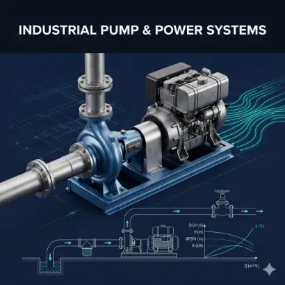
In the construction and equipment renewal cycles of industrial fluid transfer systems, pump selection is not a simple model-matching exercise based on empirical data, but a rigorous engineering deduction grounded in fluid mechanics, thermodynamics, and materials science. As the heart of the piping network, the physical specifications and performance parameters of an industrial pump directly dictate the system’s operational stability, energy consumption levels, and subsequent maintenance intervals. When initial parameter evaluations deviate from actual physical conditions, fluid equipment will inevitably experience severe overloads, sharp declines in system efficiency, and potentially destructive mechanical failures and unplanned downtime.
This guide provides an in-depth technical breakdown of the
Core Engineering Foundations of Industrial Pump Selection
Constructing a highly efficient and long-term stable fluid transfer system requires engineers to view the pump as a controlled node within the piping ecosystem, rather than an isolated mechanical device. A pump’s actual operating state is not unilaterally determined by its nameplate parameters, but by the intersection of the pump’s performance boundaries and the network’s physical resistance characteristics. Therefore, the core of selection lies in accurately constructing the system characteristic curve and achieving optimal alignment with the equipment performance curve under varying conditions.
Step 1: Defining the Physical and Chemical Boundaries of the Pumped Medium
The objective attributes of the transferred medium constitute the absolute starting point for fluid engineering design. The chemical aggressiveness, thermodynamic state, and rheological properties of the fluid directly impose physical constraints on pump materials, shaft seal structures, and hydraulic models.
The Decisive Impact of Fluid Chemistry on Pump Materials
The chemical composition and pH level of the fluid dictate the metallurgical selection for wetted components, including the volute, impeller, diffuser, and shaft. Neutral clean water or low-corrosion industrial circulating water typically utilizes standard cast iron or ductile iron to balance mechanical strength and economy. However, when the medium transitions to acidic solutions, alkaline liquids, or brines containing specific halogen ions (such as chlorides), the oxide layer on standard cast iron is rapidly destroyed. Under these conditions, alloy materials must be selected based on the Pitting Resistance Equivalent Number (PREN). For instance, austenitic stainless steel (304 or 316) is suitable for moderate corrosive environments; whereas in high-concentration chloride or strong acid applications, duplex stainless steel (e.g., 2205) or specialized Hastelloy must be deployed. Material compliance directly determines the equipment’s tensile strength degradation cycle in chemically corrosive environments.
Operating Temperature Requirements for Mechanical Seals and Cooling Systems
The operating temperature of the fluid not only affects its dynamic viscosity and density but also determines its saturated vapor pressure within the system. As temperature rises, the vaporization threshold of the liquid decreases, imposing extremely stringent requirements on the system’s Net Positive Suction Head Available (NPSHa). Mechanically, the temperature limit for standard elastomers (like NBR or FKM) typically ranges from 80°C to 120°C. When the medium temperature exceeds this physical critical point, the sealing faces of the stationary and rotary rings will suffer thermal deformation or dry-friction damage due to the superposition of friction heat and medium heat. In such scenarios, high-temperature metal bellows mechanical seals must be configured, and external forced cooling flush plans (such as Plan 21 or Plan 53 systems) must be introduced in accordance with industrial standards (e.g., API 682) to lower the ambient temperature within the seal chamber and ensure axial seal integrity.
Selection Constraints of Dynamic Viscosity and Solid Particles on Impeller Structures
The dynamic viscosity of a fluid determines the internal frictional shear forces generated as it flows through the pump chamber. For Newtonian fluids, when the kinematic viscosity exceeds 20 cSt, the internal hydraulic losses of a centrifugal pump increase significantly, leading to flow attenuation, head reduction, and a sharp rise in shaft power. During engineering selection, standard clear-water performance curves must be derated using viscosity correction charts from the Hydraulic Institute (HI). Furthermore, the hardness, diameter, and mass concentration of suspended solid particles dictate the physical morphology of the impeller. Pure fluids are suited for closed impellers, which offer extremely high hydraulic efficiency; however, when the fluid contains large solid particles or long-fiber materials, hydraulic efficiency must be partially sacrificed to prevent physical blockages by utilizing semi-open or fully open impellers, alongside hardening and wear-resistant treatments for the impeller wear rings.
Step 2: Accurate Calculation of Flow Rate (Q) and Total Dynamic Head (TDH)
Flow rate (Q) and Total Dynamic Head (TDH) are rigid mechanical work requirements imposed by the piping network’s physical conditions. The acquisition of these parameters must rely on rigorous mathematical modeling and network resistance calculations; any estimations based on rule-of-thumb can cause the system to operate outside safe envelopes.
Measurement Criteria and Margin Setting for System Rated Flow
Flow rate refers to the volume or mass of fluid the system needs to transfer per unit of time. In industrial processes, the baseline rated flow is determined by the maximum peak consumption of terminal reactors, cooling towers, or irrigation networks. If the system features multiple parallel consumption nodes, the comprehensive maximum flow must be calculated based on the concurrent usage probability. Engineering specifications generally recommend adding a 10% design margin to the calculated net flow to accommodate future capacity expansions or flow cross-section reductions caused by pipe scaling. However, margin settings must be strictly controlled; excessively inflating flow parameters will cause the selected pump’s rated operating point to deviate from the system’s actual requirements.
Mathematical Calculation of Static Head and Friction Loss
Total Dynamic Head (TDH) represents the effective mechanical energy a pump must impart to a unit weight of fluid to overcome gravitational potential energy differences and physical system resistance. Total head is not merely the difference in elevation; its calculation formula comprises both static head and dynamic (friction) head. Static head is the absolute vertical elevation difference between the suction liquid level and the discharge point. The calculation of dynamic head requires the application of the Darcy-Weisbach equation. Engineers must quantify the continuous friction loss in straight pipe sections and calculate the local resistance losses combined with the equivalent lengths of all valves, elbows, and reducers in the network. Additionally, if terminal equipment requires a specific opening pressure (e.g., pressurized nozzles), this physical pressure must be converted into equivalent liquid column height and factored into the TDH.
Calibration and Alignment of the Q-H Curve and Best Efficiency Point (BEP)
Once the required calculated flow and total head are obtained, the core subsequent step is to plot these coordinates as a duty point on the performance curve provided by the
Step 3: Evading Cavitation – System Check for Net Positive Suction Head (NPSH)
Cavitation is the most destructive fluid dynamic phenomenon in centrifugal pump operations. It not only causes a precipitous drop in equipment performance but also physically destroys the core metal components inside the pump casing in a very short time. Preventing cavitation is a rigid compliance check that fluid engineers must complete during the piping design phase.
The Physical Causes of Cavitation and Its Destructive Mechanism on Pump Structures
According to thermodynamic principles, every fluid has a fixed saturated vapor pressure at a specific temperature. When fluid is drawn into the pump and passes through the lowest-pressure zone at the impeller inlet, if the absolute pressure drops below the fluid’s vapor pressure at its current temperature, the liquid will experience localized boiling, releasing a massive amount of micro-bubbles. As these bubbles travel with the high-speed fluid into the high-pressure zones towards the impeller periphery, the sudden external pressure surge causes them to collapse rapidly (implode). The instant of bubble collapse generates microscopic high-speed jets and extreme localized temperatures, striking the metal surfaces of the impeller and volute at high frequencies with pressures reaching hundreds of megapascals. Long-term stress fatigue leads to metal lattice rupture, manifesting as severe spongy or honeycomb-like pitting on the surface.
Calculation Formulas for NPSHr and NPSHa
The engineering logic for preventing cavitation involves comparing two independent physical quantities: the pump’s inherent anti-cavitation capability versus the pressure environment provided by the system piping. Net Positive Suction Head Required (NPSHr) is an inherent parameter derived by the equipment manufacturer through physical testing on a test bed. It represents the minimum energy margin above vapor pressure that the fluid must possess before entering the impeller to avoid cavitation. Net Positive Suction Head Available (NPSHa) is the actual fluid energy the current piping arrangement can deliver to the suction port. The formula for NPSHa is: NPSHa = (Atmospheric Pressure – Fluid Vapor Pressure) / (Fluid Density × Gravity) + Static Suction Head – Suction Pipe Friction Loss. Atmospheric pressure is strictly affected by the installation altitude, while fluid vapor pressure increases exponentially with rising temperature.
Industrial Engineering Methods to Enhance System NPSHa
The compliance condition for ensuring safe pump operation is: the system’s NPSHa must be strictly greater than the equipment’s NPSHr, typically requiring a physical safety margin of at least 0.5 meters (NPSHa > NPSHr + 0.5m). If calculation results indicate the piping network fails this condition, engineers must physically intervene on the system side. Common adjustment methods include: lowering the pump’s geometric installation height to increase positive static head; increasing the nominal diameter (DN) of the suction pipe and minimizing suction-side valves and elbows to drastically reduce friction losses; or, if process conditions permit, lowering the fluid inlet temperature via an upstream heat exchanger, thereby significantly depressing the medium’s vapor pressure.
Step 4: Power Source Matching and Life Cycle Cost (LCC) Evaluation
The stability of the fluid equipment’s power system guarantees the system’s ability to operate continuously without stalling under extreme load conditions. The output characteristics of electric drives versus internal combustion engines differ fundamentally, and their matching logic is entirely distinct. Simultaneously, as a core B2B industrial equipment procurement decision, the evaluation of Total Life Cycle Cost far outweighs the initial equipment purchase price.
Shaft Power and Motor Capacity Calculation in Electric Drive Systems
In facilities with stable three-phase industrial grids, asynchronous motors are the standard configuration. The Brake Horsepower (BHP) of a pump refers to the pure mechanical power the pump shaft must absorb. BHP is directly proportional to the system’s flow rate, Total Dynamic Head, and the specific gravity (relative density) of the medium, and inversely proportional to the pump’s hydraulic efficiency. If a motor is selected based on the specific gravity of clear water (1.0), but the actual transferred medium is high-density slurry (specific gravity 1.3), the motor will immediately enter a severe overload state. Industrial compliance dictates that after calculating the shaft power at the maximum duty point, a Service Factor must be applied to the electric motor. For low-power motors, the margin is typically 20% to 25%; for high-power motors, the margin is kept around 10% to 15% to absorb extra loads caused by grid voltage fluctuations and transient fluid resistance spikes.
Diesel Engine Torque Matching Logic in Off-Grid Environments
In off-grid scenarios such as extensive agricultural drainage, municipal emergency flood control, or remote mine dewatering lacking electrical infrastructure,
The Core Metric for B2B Procurement: Life Cycle Cost (LCC) Analytical Model
B2B industrial equipment procurement decisions should not be constrained by initial commercial quotations. According to systems engineering theory, the Life Cycle Cost (LCC) model of a pump is an aggregation of multiple dynamic costs. The formula is expressed as: LCC = Initial Investment Cost (Cic) + Installation and Commissioning Cost (Cin) + Energy Consumption Cost (Ce) + Operation Labor Cost (Co) + Routine Maintenance Cost (Cm) + Downtime Loss (Cd) + Environmental and Disposal Cost (Cenv). Over a pump’s operational lifespan of ten to twenty years, initial investment costs typically account for only about 10% of the total LCC, whereas energy consumption costs (Ce) often exceed 80%. Therefore, selecting a high-efficiency pump operating precisely at its Best Efficiency Point (BEP) through rigorous technical calculations may require a higher initial budget to acquire advanced, precision-machined hydraulic models. However, the electrical or fuel savings realized over tens of thousands of operating hours will exponentially offset the initial equipment price difference.
Step 5: Outputting a Standardized Technical Data Sheet
All aforementioned physical deductions and mathematical calculations must ultimately be translated and solidified into standardized engineering documents. The engineering Technical Data Sheet is the sole objective baseline for technical alignment between the purchasing entity and the equipment manufacturer. A Data Sheet conforming to industrial standards such as API 610 or ISO 13709 should clearly and unambiguously define the following parameter sets: detailed thermodynamic and chemical fluid properties (medium name, concentration, temperature extremes, specific gravity, viscosity); rigid system operating parameters (rated flow, minimum continuous stable flow, total head); system constraint boundaries (suction flange pressure, NPSHa); equipment structural constraints (metallurgical requirements for casing and impeller, mechanical seal types and flush plans); and power unit specifications (voltage/frequency or engine displacement requirements). The standardization level of this document directly dictates the accuracy of supplier proposals and the reliability of the final engineering delivery.
Frequently Asked Questions (FAQ): Core Concerns in B2B Engineering Implementation
Based on actual engineering feedback from industrial sites, the following addresses typical technical concerns faced by engineers and equipment supervisors during pump system commissioning and retrofitting.
Q1: What are the physical reasons for noticeable overheating and vibration in pipeline pumps during actual operation? Abnormal overheating and high-frequency bearing housing vibrations in fluid equipment generally result from the actual operating point deviating severely from the design Best Efficiency Point (BEP). When actual network resistance is significantly higher than the pump’s design head, the pump operates in a minimum flow region. The fluid inside the casing undergoes massive internal recirculation and friction; mechanical energy cannot convert to kinetic energy and is instead released as heat, causing the pump casing temperature to rise. Conversely, if network resistance is extremely low, the pump will “run off the curve” into an excessive flow region. This causes a surge in required motor output torque, leading to coil overheating. Concurrently, radial unbalanced forces on the impeller reach their peak, forcing minor shaft deflection that triggers violent mechanical vibrations and accelerates seal wear.
Q2: Under what conditions is it necessary to configure Variable Frequency Drives (VFD) for industrial fluid systems? A Variable Frequency Drive (VFD) is not a universal solution for improving energy efficiency across all fluid systems. The energy-saving logic of a VFD is based on the Affinity Laws of fluid mechanics: a pump’s flow rate is directly proportional to its speed, while the consumed shaft power is proportional to the cube of the speed. Therefore, configuring a VFD to reduce speed yields significant power reductions only when the process system’s terminal flow demand exhibits distinct dynamic fluctuations (e.g., cooling loads changing with day/night temperatures) AND when friction head dominates the system’s total dynamic head (with low static head). For systems that must overcome extremely high fixed static heads (e.g., high-rise water supply or deep-well lifting) and require 24/7 full-load constant flow, running the motor Direct-On-Line (DOL) at a constant speed generally results in higher overall transmission efficiency.
Q3: How can instrumentation data and physical phenomena accurately diagnose pump cavitation in a system? When cavitation occurs, the external physical manifestations of the fluid system are highly distinct. Auditorily, the interior of the pump will emit popping or crackling sounds, resembling a large volume of gravel or hail impacting a metal container at high frequencies. In terms of instrumentation data, due to the vapor bubble clouds restricting the cross-sectional flow area within the impeller passages, the flow meter will display a precipitous drop or severe cyclical fluctuations in flow rate. Simultaneously, the discharge pressure gauge pointer will swing violently and erratically. If the equipment is dismantled for structural inspection, deep, sponge-like or honeycomb-like metal pitting will typically be observed on the leading edges of the impeller vanes and the inner walls of the volute—this is definitive physical evidence of material fatigue failure caused by the high-frequency impact of micro-jets.
Conclusion
In summary, the selection of industrial pipeline pumps is not a simple product catalog search, but a comprehensive engineering calculation process encompassing fluid dynamic boundary analysis, thermodynamic system verification, and material resistance evaluation. Accurately defining the physical and chemical properties of the fluid medium is a prerequisite for establishing equipment metallurgy. Rigorous deduction of flow rates and total system resistance is the core rule for anchoring the high-efficiency operating zone. Furthermore, strict verification of NPSH boundaries and precise matching of power source characteristics are the cornerstones for ensuring the entire transfer network remains free from mechanical collapse over the long term. During the equipment planning phase of B2B industrial projects, consistently relying on the Life Cycle Cost (LCC) model as a benchmark and strictly outputting standardized Technical Data Sheets is the only scientific pathway to enhancing overall system efficiency and reducing unplanned maintenance expenditures.
Get A Quote

Get A Quote
0 Comments