
How Does a Centrifugal Pump Work? Components & Selection Basics
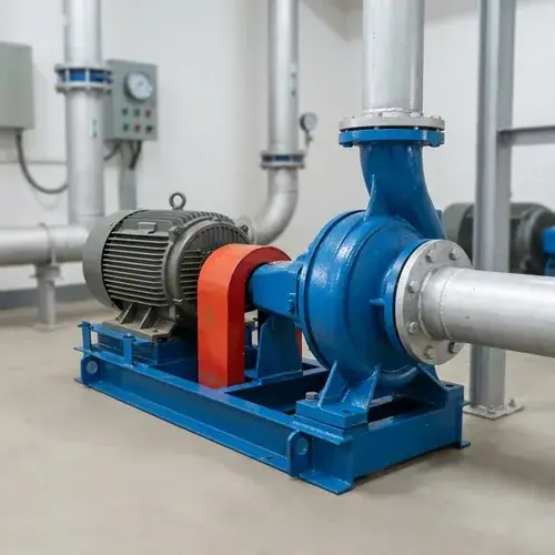
How does a centrifugal pump work? In simple terms, a centrifugal pump converts rotational mechanical energy from a motor into fluid velocity, then into pressure energy. The spinning impeller throws liquid outward, and the casing captures that speed as usable discharge pressure. That sounds simple enough until you sit across the table from a supplier who hands you a pump curve and expects you to confirm a duty point. At that moment, you need more than a textbook definition — you need to connect how the pump behaves inside to how your system demands flow, head, and reliability.
This guide is written for exactly that situation. Whether you’re an EPC engineer prepping a data sheet, a procurement manager comparing pump quotes, or a technical distributor fielding customer questions, this page will walk you through the real engineering logic behind centrifugal pump operation. We’ll cover the step‑by‑step energy conversion, the components that most often fail (and why), how flow and head are generated under system resistance, and how to read pump curves well enough to avoid the two most expensive mistakes: selecting a pump that will cavitate, and operating one far from its best efficiency point.
By the time you finish, you’ll have a practical mental model of centrifugal pump behavior — the kind that lets you ask the right questions before you sign a purchase order, not after the installation fails.
Quick Answer: How a Centrifugal Pump Moves Liquid
A centrifugal pump adds energy to a fluid by spinning it at high speed. The liquid enters the impeller eye at the center, gets flung outward along the curved vanes, and leaves the impeller tip at much higher velocity. The volute casing (or diffuser) then slows that fast‑moving liquid down, which converts velocity into static pressure — the head your system needs to overcome elevation, friction, and pressure vessel resistance. The pump doesn’t create a fixed volume per revolution; it creates a continuous flow whose magnitude depends on system back‑pressure. That’s the fundamental difference from a positive displacement pump, and it’s the reason centrifugal pump performance must always be evaluated against a system curve, not just a single max‑head number.
Scope of This Guide
This article focuses exclusively on the single‑stage overhung centrifugal pump family — the workhorse behind most industrial water supply, HVAC, process transfer, irrigation, fire protection, and dewatering applications. We’ll touch on double‑suction and multistage variants where they clarify working principles, but the deep engineering logic centers on what an impeller and volute do together. We will not dive into full positive displacement pump theory, detailed motor rewinding, or consumer‑grade circulator troubleshooting. This is a B2B sourcing‑oriented engineering reference, not a general fluid mechanics textbook. Every explanation ties back to a procurement or operational decision you’ll need to make.
What Is a Centrifugal Pump?
A centrifugal pump is a rotodynamic machine that increases a fluid’s kinetic energy and then converts most of it into pressure head. The U.S. Hydraulic Institute defines it as a pump that uses a rotating impeller to add energy to the fluid — the term “centrifugal” referring to the outward radial motion that results from rotation. In industrial practice, you’ll find these pumps handling clean water, mildly contaminated wastewater, chemicals, hydrocarbons, and even abrasive slurries (with special materials).
They dominate the pump market for a reason: relatively simple construction, wide flow and head coverage, smooth continuous flow, and easy speed control via VFD. Their main limitation is that they are not self‑priming in their standard configuration — the casing must be filled with liquid before starting — and they struggle with highly viscous fluids, where efficiency drops sharply.
How Does a Centrifugal Pump Work Step by Step?
Let’s follow a drop of water through a standard end‑suction centrifugal pump. Think of this as a four‑stage energy chain: suction, acceleration, conversion, discharge. Each step has a direct impact on whether your pump selection survives the first year of operation.
How the Impeller Creates Velocity
The liquid enters the rotating impeller at its center — the impeller eye — where pressure is lowest. From there, the curved vanes grab it and force it to move in a circular path while accelerating radially outward. By the time the fluid reaches the impeller tip, it has picked up significant tangential velocity — often in the range of tens of meters per second, depending on impeller diameter and speed.
This is a critical engineering point: the impeller’s job is to increase velocity, not pressure. The discharge pressure you measure at the pump flange doesn’t come from the impeller directly; it comes from what happens in the casing. Misunderstanding this leads buyers to oversize impellers, hoping for higher pressure, when what they actually need is a different casing design (or a multistage pump if the single‑stage head limit is reached).
How the Volute or Diffuser Converts Velocity into Pressure
The high‑velocity fluid leaves the impeller tip and enters the volute, a spiral‑shaped chamber whose cross‑sectional area increases gradually. As the liquid moves along this expanding path, its velocity must decrease (continuity equation), and by Bernoulli’s principle, that kinetic energy loss becomes pressure energy. A diffuser works similarly — a ring of stationary vanes around the impeller that decelerate the fluid and direct it into a pressure‑collection chamber.
A poorly designed volute or diffuser will not recover velocity efficiently, wasting energy as turbulence and heat. In sourcing terms, this is one reason why two pumps with identical impeller diameter and speed can show measurably different head and efficiency on the test stand: one manufacturer optimized the hydraulic passage, the other just copied a pattern. Ask for a hydraulic performance test curve, not a catalog generic curve, when efficiency is critical.
Why Centrifugal Pumps Usually Require Priming
A centrifugal pump cannot pump air — the impeller just spins in a gaseous void without generating enough suction to lift liquid from a lower level. That’s why standard end‑suction and split‑case pumps need to be primed: the casing and suction pipe must be completely filled with liquid before startup. If you start a dry pump, the mechanical seal runs without lubrication and can fail quickly; the impeller won’t build pressure; and the entire system sees a dead‑head condition.
There are exceptions: self‑priming centrifugal pumps have a built‑in reservoir and recirculation design that lets them pull a vacuum and draw liquid up, which is useful for sump drainage or tanker unloading. But they trade some efficiency and cost for that capability. If your application requires true dry‑suction lift, consider a self‑priming pump explicitly — we compare the engineering trade‑offs in depth in our Self‑Priming Pump vs Centrifugal Pump Engineering Differences, System Design Rules & Complete Selection Guide.
Main Centrifugal Pump Components and Their Functions
A centrifugal pump is more than an impeller and a casing. The components you approve during supplier review — bearings, seal, shaft, wear rings — determine whether the pump runs for 5 years without intervention or fails every quarter. Here’s a quick functional map before we get into the details.
Open vs Semi‑Open vs Closed Impellers
| Impeller Type | Construction | Typical Use | Buyer Consideration |
|---|---|---|---|
| Closed | Two shrouds (front and back) enclosing vanes | Clean water, light chemicals, standard industrial pumping | Highest efficiency; sensitive to solids — anything that can lodge between shrouds and casing will seize or wear. |
| Semi‑open | Rear shroud only; front of vanes exposed | Mildly dirty water, small solids, occasional sludge | Tolerates small suspended solids better; slightly lower efficiency; clearance between vane tip and casing wear plate must be maintained or performance drops. |
| Open | No shrouds; vanes mounted on hub | Slurries, paper stock, viscous or stringy materials | Lowest efficiency; handles solids but needs frequent clearance adjustment and wear plate replacement. |
Closed impellers deliver peak efficiency — often above 80% in many large double‑suction pumps, depending on design — but they are unforgiving with solids. If you’re pumping anything dirtier than clean river water, and the supplier insists on a closed impeller without showing you a solids‑handling record, ask to see a semi‑open alternative. The efficiency penalty is often just a few percentage points, and that pays back quickly in reduced unplanned downtime.
Volute Casing vs Diffuser Design
Most industrial centrifugal pumps use a volute casing: a single spiral chamber that collects fluid from the impeller and guides it to the discharge nozzle. Volutes are cost‑effective, simple to cast, and work well across a range of flows.
Diffuser‑style pumps insert a stationary ring of guide vanes around the impeller. These vanes redirect the fluid and control its deceleration more precisely, which can yield higher head per stage and better part‑load efficiency in multistage designs. The trade‑off: diffuser pumps are more sensitive to off‑design operation — at very low flow, the vane angles no longer match the fluid exit angle, causing recirculation and vibration. For a single‑stage general‑service pump, you almost always want a volute. For a high‑pressure multistage pump, diffusers become the standard.
Mechanical Seals vs Packing
The shaft must pass from the liquid‑filled casing to the dry atmospheric side. How you seal that passage defines a large chunk of your maintenance budget.
- Gland packing: Braided rings compressed around the shaft. Cheap, forgiving of shaft misalignment, but needs controlled leakage (a few drops per minute) for cooling and lubrication. Not acceptable in zero‑leakage or hazardous fluid services.
- Mechanical seal: Two lapped flat faces — one rotating with the shaft, one stationary in the gland plate — form a micro‑thin fluid film that seals dynamically. Leakage is negligible; the seal handles pressure and temperature much better than packing. For many industrial services—particularly those involving clean or mildly contaminated liquids, pressures above a few bar, or any fluid where leakage control is critical—a cartridge mechanical seal is the standard recommendation. It provides negligible leakage, handles higher temperatures and pressures, and reduces maintenance frequency compared to packing. That said, in low‑pressure clean‑water applications where occasional drip leakage is tolerated and initial cost is a constraint, gland packing or a component seal can still be a valid engineering choice if the maintenance schedule accounts for it. The seal face materials — SiC, carbon, tungsten carbide — must be matched to the pumped fluid’s chemistry, solids content, and temperature, or the seal will fail prematurely.
If a supplier proposes only a packed gland as the base option for a project where leakage control or process uptime matters, dig deeper. They’re either cutting corners or targeting a commoditized price point where long‑term reliability isn’t expected.
How Flow, Head, and Pressure Are Generated
This is where procurement language starts to matter. In a supplier meeting, “flow” means the volume of liquid the pump can move per unit time, typically m³/h or GPM. Head is the amount of energy added to each unit weight of fluid, expressed in meters (or feet) — it’s not a pressure reading at the discharge flange, at least not directly. Head includes the energy needed to lift fluid, overcome piping friction, and push against any terminal pressure. The discharge pressure (bar, psi) is a consequence of head and the fluid’s specific gravity.
An important distinction: the centrifugal pump generates a certain head at a given flow; the system determines what flow actually occurs. The pump curve shows head as a function of flow. The system curve shows head required as a function of flow (typically a quadratic curve based on friction). The intersection is the operating point. If you throttle a discharge valve, you’re steepening the system curve and moving the operating point left on the pump curve — less flow, higher head. This is why a pump that “should” deliver 200 m³/h may only deliver 160 m³/h in a real installation with long, small‑diameter piping.
To get a deeper practical walk‑through of sizing and system curve construction, refer to How to Select the Right Pump: Complete Flow, Head, Pipe Size & System Design Guide.
A quick reference table for the buyer:
| Term | What It Tells You | Common Confusion |
|---|---|---|
| Flow (Q) | Volume moved per unit time | Capacity at zero head is not real; it’s theoretical. |
| Total Dynamic Head (TDH) | Energy added by pump, accounting for elevation, friction, pressure | Often mistaken for discharge gauge reading; a high gauge pressure does not automatically mean high TDH if suction pressure is poor. |
| Static Head | Elevation difference only | Ignores friction — useless alone for selection. |
| NPSH | Net suction head available to prevent cavitation | Critical but often skipped; we treat this in detail below. |
Understanding Pump Curves and Efficiency
A pump curve is the single most powerful document in centrifugal pump selection. It plots head vs. flow, usually with overlays for efficiency, power consumption, and required NPSH (NPSHr). The Best Efficiency Point (BEP) is the flow rate at which hydraulic losses are minimized and the pump operates most smoothly. Ideally, your specified duty point should fall within 80–110% of BEP flow. Operating outside that band doesn’t immediately destroy the pump, but it invites higher radial loads, vibration, and lower seal/bearing life.
What Happens When a Pump Operates Away from BEP
At very low flow (toward shut‑off), the impeller is churning fluid that has nowhere to go; recirculation between impeller and casing causes pressure pulsations, increased radial load on the shaft, and rapid temperature rise. At very high flow (run‑out), NPSHr spikes, suction pressure collapses, and the pump may cavitate or the motor overload. In both extremes, vibration amplitudes climb, seals wear faster, and bearing L10 life drops significantly.
The hidden cost is energy. A pump running far from BEP wastes a disproportionate amount of energy; the efficiency at, say, 60% of BEP flow can be drastically lower than the BEP rating. Over a 24/7 operation, that efficiency gap often dwarfs the savings from a premium‑efficiency motor alone. That’s why selecting a pump that’s “over‑sized for future expansion” often backfires. We expand on this system‑level reality in Pumps vs Motors: Why “High‑Efficiency Motor” Alone Won’t Reduce Your Energy Bill.
Why System Design Affects Energy Cost More Than Motor Efficiency
A 2% improvement in motor efficiency saves a small amount of power. Moving the pump operating point from a low‑efficiency zone to near BEP saves far more. The biggest energy lever in a centrifugal pump system isn’t the motor efficiency class — it’s the system curve: pipe diameter, valve selection, and correctly matching the pump to actual required head. When you’re comparing quotes, don’t fixate on IE3 vs IE4 motor alone; ask the supplier to show where the pump operates on its efficiency curve for your specified duty.
NPSH and Cavitation Basics
NPSH stands for Net Positive Suction Head. NPSHa (available) is the absolute head at the pump suction flange minus vapor pressure — it’s a system property that you calculate. NPSHr (required) is the minimum suction head the pump needs to avoid cavitation, and it comes from the pump curve (determined by the manufacturer through a cavitation test). For safe operation, NPSHa must exceed NPSHr by a margin — typically 0.5 to 1 meter for clean water, more for hot liquids or light hydrocarbons.
When NPSHa drops below NPSHr, the liquid at the impeller eye starts to boil locally; tiny vapor bubbles form and then violently collapse as they move into higher‑pressure regions. This implosion can erode impeller and casing surfaces, sounding like gravel passing through the pump. Chronic cavitation destroys hydraulics and can crack impeller vanes within months.
From a procurement perspective, if the supplier doesn’t ask you for suction conditions — static lift, suction pipe length and diameter, fluid temperature — be suspicious. They should also provide the NPSHr curve; if that curve is missing or starts at a suspiciously low value, request a witnessed cavitation test or at least a test report from a recognized hydraulic lab.
Common Centrifugal Pump Types and Where They Are Used
Here’s a quick selection shortcut for the main industrial centrifugal configurations you’ll encounter:
| Pump Type | Typical Flow / Head Range | Best Applications | Key Limitation |
|---|---|---|---|
| End‑Suction | Up to ~500 m³/h, head up to ~150 m | General water supply, HVAC, light industry | Not self‑priming; limited suction lift. |
| Double‑Suction | 200–10,000+ m³/h, head up to ~160 m | Cooling water, irrigation, large transfer | Larger footprint; higher cost; not for dirty liquids without protection. |
| Multistage | Up to ~300 m³/h, head 100–600+ m | Boiler feed, high‑pressure wash, RO plant feed | Sensitive to solids; maintenance more complex. |
| Inline / Pipeline | Moderate flow, up to ~160 m head | Building services, booster sets, confined plant rooms | Suction directly in line; limited access for repair. |
| Self‑Priming | Up to ~200 m³/h, head to ~60 m | Dewatering, sewage lift stations, tanker unloading | Lower efficiency; larger casing; periodic re‑prime maintenance. |
For a deeper comparison of single‑stage vs multistage, including when the added cost of multiple stages pays off, see Single Stage vs Multistage Pump: Which One Should You Choose for Pressure, Flow, and Energy Cost?.
What Buyers Should Verify Before Selecting a Centrifugal Pump Supplier
In industrial pump sourcing, approving equipment on catalog data alone can create expensive problems if the delivered hydraulic performance does not match the tested performance on site. Here’s the due‑diligence checklist we recommend for B2B buyers.
Supplier Verification Checklist
- Tested pump curve: Ask for a hydraulic performance test report per ISO 9906 Grade 2 or 1, not a generic catalog curve. The test data should cover at least 5 points from shut‑off to run‑out, with clear BEP marking.
- Material certificates: For cast iron, stainless steel, and duplex components, request mill test certificates (EN 10204 3.1 or equivalent).
- Mechanical seal specification: Confirm seal make, model, face materials, and elastomer. Steer clear of unbranded generic seals — ask for a seal from a known manufacturer with traceable specifications, like John Crane, EagleBurgmann, or an approved equivalent.
- Impeller balancing: The rotor should be dynamically balanced in accordance with recognized standards (such as ISO 21940). Acceptable balance grades vary by pump size, rotational speed, and service duty; verify that the target balance grade matches your project specification or the supplier’s documented standard for the pump category. Ask for the balance report.
- Casing pressure test: The casing should be hydro‑tested to 1.5 times the rated working pressure and the report supplied.
- Bearing type and brand: Confirm bearing numbers and manufacturer (SKF, NSK, FAG, etc.). Bearings without clear manufacturer markings or traceability increase reliability risk.
- Export packaging: Pumps must be secured on wooden pallets or in crates, motor flange blocked, bare metal surfaces protected with anti‑rust oil, and desiccant bags included if shipping to humid climates. Ask for packaging photos of similar previous shipments.
- Lead time commitment: Get a written lead time with production milestones. “4–6 weeks” means little if you haven’t locked in a confirmed shipment date.
RFQ Data Checklist
Provide these minimum data points in any RFQ for a centrifugal pump:
- Flow rate (m³/h or GPM), required head (m or ft)
- Liquid: clean water, wastewater, chemical type, temperature, viscosity, solids content and size
- NPSHa at pump suction (calculated)
- Power supply: voltage, phase, frequency, ambient temperature
- Preferred materials for casing, impeller, shaft
- Mechanical seal or packing preference
- Required standards: ISO 9906, ANSI/HI, API 610 if applicable
- Documentation: test curve, material certs, dimensional drawing, installation manual
- Target delivery date and shipment method
- Inspection requirements: factory visit, witnessed test, or only report review
FAQ
These questions come up repeatedly when engineers and buyers move from catalog browsing to actual centrifugal pump selection. The answers below focus on practical engineering and procurement considerations rather than textbook definitions.
Why does a centrifugal pump lose prime?
A centrifugal pump loses prime when air enters the casing or suction line, breaking the liquid column. Common causes: a leaking foot valve or check valve, a dry suction tank, or an air leak in the suction pipe flanges or mechanical seal. Standard centrifugal pumps cannot re‑prime themselves — they will spin in air, overheat the seal, and deliver no flow. You must vent the casing manually or use a vacuum priming system.
What creates pressure inside a centrifugal pump?
Pressure is created when the high‑velocity liquid leaving the impeller is slowed down in the volute or diffuser. That deceleration converts kinetic energy into static pressure. The impeller itself generates velocity; the casing generates pressure. If you open the discharge valve fully against a low‑resistance system, pressure will be low and flow high; if you close the valve, flow drops and pressure rises — up to the shut‑off head limit.
What is the difference between flow and head?
Flow is how much liquid moves per unit time. Head is the energy added per unit weight — it represents the total resistance the pump overcomes, including lift height, friction, and pressure difference. Two different pumps can deliver the same flow at wildly different heads; what matters is whether the pump’s head‑flow curve intersects your system curve at the desired capacity. In RFQ terms, never specify only flow — you’re asking for a pump that can be completely wrong.
Can centrifugal pumps handle solids?
Some can, some cannot. Standard closed‑impeller pumps clog easily with rags or stones. Open or semi‑open impellers with wear plates are designed for dirty water and small solids. For larger solids, you typically need a non‑clog sewage pump with a specifically shaped impeller and large passage diameter. If your liquid contains solids, tell the supplier the maximum solid size, shape, and concentration, and ask for a solids‑handling reference or cutwater clearance design detail.
Why is pump efficiency important for lifecycle cost?
The pump’s hydraulic efficiency directly determines energy consumption. In a continuous‑duty water supply application, a 10‑point efficiency difference can translate into substantially higher electricity costs over the pump’s life, far exceeding the initial purchase price. Additionally, a pump operating near BEP runs cooler and with lower radial loads, extending bearing and seal life. Cheap pumps that operate chronically off‑BEP are the most expensive pumps you’ll ever buy.
How do engineers choose the correct duty point?
They plot the system curve (head required vs. flow) against the pump curve and select a pump whose BEP flow is close to the desired operating flow — ideally within 80–110% of BEP. It’s not enough to look at a single head‑flow point; you must check where that point sits on the efficiency and NPSHr curves. If the duty point falls at 60% of BEP flow, you’re buying an oversized pump that will waste energy and likely vibrate. In that case, consider a different pump size or a VFD to shift the curve.
Conclusion
A centrifugal pump works because its impeller accelerates liquid and its casing captures that energy as pressure. But “how it works” only becomes useful when you connect that principle to real‑world procurement decisions: which impeller type for your liquid, whether the seal materials match your fluid chemistry, where your duty point sits on the efficiency curve, and what NPSH margin you must maintain. The pump that looks perfect in a catalog is rarely the pump that performs best in a system that was designed by committee.
Three things to carry forward into your next RFQ: always calculate NPSHa and insist on seeing the NPSHr curve, demand a factory‑tested pump curve — not a generic catalog plot — and check where your operating point lands relative to BEP. A correctly sized centrifugal pump, procured with proper verification, can run quietly and efficiently for years. An incorrectly applied one often costs you in energy, downtime, and frustration from the start.
If you’re evaluating centrifugal pump suppliers and want to understand how Liqen approaches hydraulic selection, performance testing, and documentation packages, contact our engineering team with your duty data. We are happy to provide preliminary application review and discuss the kind of performance expectations and material guidance that would apply to your project, subject to a complete duty specification and engineering evaluation.
Standards Referenced: Pump terminology and hydraulic performance testing concepts in this guide draw on publications by the Hydraulic Institute (ANSI/HI), ISO 9906, ISO 21940, and API 610 where mentioned. Buyers should refer to the latest editions of these standards and their project‑specific requirements.
Get A Quote

Get A Quote
0 Comments