
Pump Installation Checklist: Stop Cavitation, Vibration, Early Failure
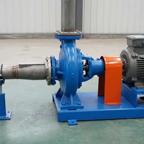
Your pump installation checklist is the difference between a pump that runs quietly for years and one that destroys its own impeller or bearings during commissioning or early service. In our field experience, a large share of early pump failures are not manufacturing defects — they are suction piping mistakes, pipe strain, soft foot, skipped alignment, or a bad startup sequence. Fix those during installation and you prevent the cavitation, vibration, seal failure, and bearing failure that drive warranty claims and unplanned downtime.
A pump that fails during commissioning costs far more than the repair. You lose production time, pay for emergency labor, and can void the manufacturer's warranty for damage caused by incorrect field installation. This guide gives you the phased checks Liqen uses — foundation and grouting, suction and discharge piping, alignment, and pre-startup commissioning — so a contractor or plant engineer can walk through the job once and hand over a machine that starts clean and stays reliable.
Before mechanical work starts, get the pump's Installation, Operation, and Maintenance (IOM) manual and confirm whether a factory-tested performance curve is included or available as a quoted document. Use this article as a working checklist, not a substitute for the manual. When the IOM and this guide conflict, the IOM wins.
Quick Answer: What Your Pump Installation Checklist Must Control
If you remember nothing else, control these five things in order:
- Foundation and baseplate: rigid, level, fully grouted, no soft foot before tightening.
- Suction piping: 5 to 10 straight pipe diameters before the flange, eccentric reducer flat side up, independently supported pipe, zero strain.
- Discharge piping: separately supported, correct valve layout, no weight or thermal load transferred to the pump.
- Alignment: precise shaft alignment up front, re-checked after piping is filled and again at operating temperature.
- Pre-startup: motor rotation verified before coupling, pump fully primed, seal flush active, suction valve 100% open, discharge cracked for start.
Get any one of these wrong and the failure shows up as cavitation pitting, seal leakage, coupling wear, or high-vibration bearing damage. The rest of this article explains exactly what to check, what to measure, and where installation teams usually skip a step.
Why Many Early Pump Failures Start at Installation
If you talk to commissioning engineers or review warranty-claim investigations, the pattern repeats itself. Liqen's service work sees it too: in our experience, a substantial share of early-life failures — the pumps returned or repaired in the first months of service — trace back to installation errors rather than factory defects. A good pump can still fail early when it is installed badly.
Pipe strain is the classic one. When suction or discharge piping does not line up with the pump flange, installers use bolts, pry bars, or chain falls to pull the pipe into place. That transfers external bending force into the pump casing. The casing distorts, shaft centerlines move out of line, bearings carry a radial load they were never designed for, and in the worst case a cast-iron foot or flange cracks. You cannot see pipe strain after the bolts are tight — you have to test for it during installation, before it shows up later as vibration.
Low NPSHa is the other silent killer. If the suction line has an elbow too close to the flange, a concentric reducer on a horizontal run, a partially open valve, or a clogged strainer, the pump may still move liquid, but the available NPSH drops below the pump's required NPSH near the impeller eye. Cavitation starts: vapor bubbles form and collapse against the impeller, causing pitting, noise, and vibration. The pump may never reach its rated flow, and the owner assumes it was undersized.
Neither of those is a pump defect. The impeller did not choose to erode; the bearing did not decide to fail. The installation forced it. That is why a working pump installation checklist protects both your warranty position and your total cost of ownership.
Phase 1: Foundation, Baseplate, and Grouting Checks
Before you connect any pipe, get the base right. A flexible or rocking baseplate turns a perfectly aligned pump into a vibration source, because the whole assembly moves under torque and hydraulic load.
The foundation should be a mass concrete pad sized for the pump, motor, and future maintenance access. Confirm the anchor bolt template matches the baseplate drilling before concrete is poured — repositioning anchors after the concrete has cured is expensive and weakens the pad. Request the dimensional baseplate drawing from the supplier before civil work; Liqen can supply it when confirmed in the order scope. Verify bolt-hole positions against that drawing before the concrete is locked in.
Level the baseplate using steel shims or leveling screws, and leave a grout fill gap under the base — check the IOM for the specified height — before tightening anchors.
Now check soft foot. Soft foot means one foot of the baseplate is not sitting flat on its shim stack, so tightening a bolt twists the frame. The field test is simple: loosen each anchor bolt one at a time and measure the foot with a feeler gauge. If the frame lifts or the gap changes, you have soft foot. Correct it with thin shims before final tightening — do not just torque the bolt and hope the twist goes away.
Once the base is level and soft foot is eliminated, pour non-shrink grout per the IOM — either epoxy or cementitious — under the full baseplate area. Grout transfers load evenly and stops the base from flexing. Work the grout into the void completely; large baseplates may need vent holes to prevent air pockets. Let the grout cure for the manufacturer's specified time before tightening anchors or doing final alignment — grout that is loaded too early never reaches full strength.
Phase 2: Suction and Discharge Piping Design Rules
Piping is where most pump installation mistakes happen. Up to this point, a pump is just a machine sitting on concrete. The moment you connect the suction and discharge lines, bad geometry and bad support start doing real damage.
Suction piping governs whether the pump cavitates. The general rule is to provide 5 to 10 pipe diameters of straight run before the suction flange. That gives the liquid a chance to settle into a uniform flow profile before it enters the impeller eye. The exact number depends on the pump's suction energy and the manufacturer's IOM, but if an elbow is bolted directly to the suction flange, you are already trading away NPSH margin.
On a horizontal suction line, use an eccentric reducer with the flat side up. A concentric reducer — or an eccentric reducer installed flat side down — lets air or vapor collect at the top of the pipe and then enter the pump as a slug. That is a classic cause of startup cavitation and mechanical seal damage. If the suction enters from above and the reducer is vertical, flat side down is correct. Most installations are horizontal, so remember: flat side up.
Discharge piping needs independent support too. The pipe must bolt up cleanly without springs, prying, or hammering the flanges together. A properly done pump piping job bolts up by hand first, then torques. Support the piping so its weight is carried by pipe stands or hangers near the pump flanges, not by the pump casing.
Expansion joints have a specific job — absorbing thermal expansion, not fixing pipe strain. If you use an expansion joint to force misaligned flanges together, you have simply moved the stress into the joint, and the pump can still receive thrust load unless that joint is tied and anchored correctly. This is one of the most misused accessories in pump installation.
| Component / Practice | Correct Method | Incorrect Method | Risk if Incorrect |
|---|---|---|---|
| Straight run before suction flange | 5 to 10 straight pipe diameters, unobstructed | Elbow, valve, or tee at or immediately before the suction flange | Non-uniform flow at the impeller eye, reduced NPSHa, cavitation |
| Reducer on horizontal suction | Eccentric reducer, flat side up | Concentric reducer, or eccentric flat side down | Air pocket collects at the top, enters the pump, damages seal and impeller |
| Pipe support | Independent pipe stands or hangers near the flanges; flanges bolt by hand | Pump casing used as pipe support; forced bolt-up with pry bars | Pipe strain distorts the casing, causes vibration, possible flange or foot cracks |
| Suction valve | Full-port valve, 100% open at startup | Undersized or partially open valve creating a pressure drop | Reduced NPSHa, cavitation, lower flow |
| Startup strainer | Temporary startup strainer sized for low pressure drop, monitored and cleaned | Fine permanent strainer left plugged near the flange | Starves the pump, liquid vaporizes, seals run dry |
If a pump is already cavitating or showing impeller pitting after startup, stop and correct the suction side before replacing parts. The deeper diagnostic process is covered in the full troubleshoot pump cavitation guide.
Phase 3: Pump and Motor Alignment Tolerances
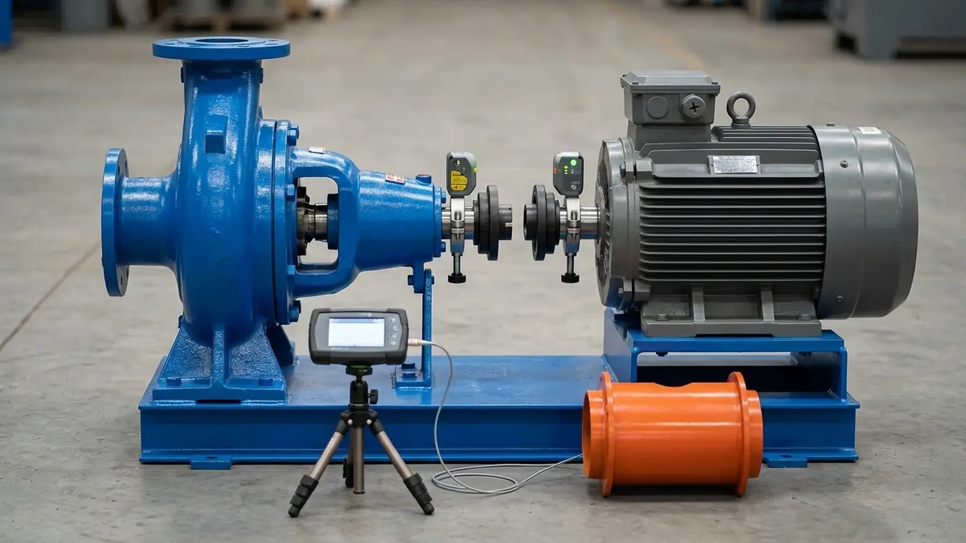
Alignment is where a small tolerance pays back in bearing and seal life. A pump and motor aligned to the tight end of the IOM tolerance can run noticeably longer between overhauls than one left at the edge of acceptable.
Misalignment comes in three forms:
| Misalignment Type | Description | Primary Damage Caused |
|---|---|---|
| Radial (parallel/offset) | Shaft centerlines are parallel but offset vertically or horizontally | Heavy bearing load, rapid bearing wear, elevated vibration at running speed |
| Angular | Shaft centerlines meet at an angle; coupling faces are not parallel | Cyclic bending of the shaft, coupling flexing, seal face pumping, early seal failure |
| Axial (end float / spacing) | Incorrect axial gap or end float between shaft ends | Thrust load on the coupling or thrust bearing, coupler wear |
The common industry myth I want to kill right here: a flexible coupling does not fix misalignment. It accommodates small thermal growth and axial float, but it still transmits the same misalignment forces into both shafts. If you hook up a badly aligned motor and rely on the coupling to absorb it, the bearings and mechanical seals take the load. The only real justification for a flexible coupling is thermal growth compensation, not sloppy installation.
Alignment usually happens in two steps. Cold alignment first: after the base is grouted and soft foot is removed, then again after the piping is connected and filled — because hydraulic and thermal load from piping can shift the shafts. Then a hot alignment check after the pump has run under load and reached operating temperature; thermal expansion moves metal, so your cold setting must anticipate that movement. The IOM gives the target tolerances and any thermal growth compensation. As an order of magnitude, many industrial pump IOMs allow around 0.05 mm (0.002 in) or better total indicator reading at the coupling hub — confirm from your manual, not from memory.
The tools are a dial indicator set (reverse dial method) or a laser alignment system. Laser is faster and less dependent on the skill of the person taking readings. A skilled technician with two dial indicators can get the same result, but with more calculations and more room for error. On remote-site commissioning where time is expensive, the cost of a laser unit is usually recovered in the first bearing it saves.
If you already have a pump vibrating and damaging bearings after installation, go back to alignment and pipe strain first — those two are the most common causes and the cheapest to correct.
Phase 4: Pre-Startup and Commissioning Checklist
By this point the pump is grouted, piped, and aligned. The final checks separate a clean startup from a dry seal or a reversed impeller.
Verify motor rotation before you couple the shafts. Run the motor momentarily — a quick bump with the coupling disconnected or the coupling element removed — and check the direction against the motor arrow or the IOM. If the direction is wrong, reverse any two supply phases at the starter (three-phase motor) with the power locked out. Never reverse rotation while the pump is connected and full of liquid.
Prime the pump before start. A centrifugal pump is not self-priming unless it is specifically designed as one; even a short run with an air-filled casing can severely damage the mechanical seal faces, because the seal may run without enough liquid to cool and lubricate them. Vent trapped air through the priming plug or vent valve until liquid flows out. On pumps with an external seal flush or barrier fluid system, start that flow before the pump rotates — the seal needs the flush even during the first few seconds.
Set the valves in the right order. Suction valve goes 100% open. The discharge valve starts cracked open or per the IOM start procedure, then opens fully as the system comes up to pressure; avoid dead-heading the pump. Check that the suction strainer is clean and the discharge check valve is oriented correctly.
Go through this pre-startup sequence and sign each item off:
- Foundation inspected and grout fully cured per manufacturer
- Baseplate level, anchor bolts torqued in sequence
- Soft foot eliminated and re-checked after piping
- Suction and discharge piping independently supported, no pipe strain
- Eccentric reducer flat side up on horizontal suction line
- Suction valve full-port and 100% open
- Pump fully primed, air vented, seal flush lines open and flowing
- Motor rotation verified uncoupled, correct direction
- Shaft alignment verified cold and after piping, and hot after warm-up
- Oil or grease levels checked, coupling guard installed and secure
- Pressure gauges connected at pump suction and discharge
- Baseline vibration and bearing temperature recorded for future comparison
Take baseline readings at the first clean startup and write them into the commissioning record. When vibration climbs later, you need today's numbers to know whether the problem is new or was always there. If the seal keeps leaking after startup, the priming and flush sequence is where a lot of avoidable damage hides. Run through the steps in this extend mechanical seal life guide before blaming the seal supplier.
Top 3 Installation Mistakes That Cause Cavitation and Vibration
The full checklist is above. These are the three mistakes I see most often in the field, and all of them are cheap to prevent once you know to look for them.
1. Starving the pump on the suction side. An elbow too close to the flange, a concentric reducer on a horizontal run, a throttled suction valve, or a plugged startup strainer all reduce NPSHa. The pump may still deliver some flow while it cavitates, and an operator may not recognize the noise until the impeller is already pitted. Check the entire suction path from the source to the flange before the first start.
2. Forcing flanges together. If the pipe does not line up, fix the pipe. Do not use the flange bolts to pull it into place. Pipe strain does not leak on the floor like a bad seal; it quietly loads the casing and bearings until something fails. The standard verification test: once the piping is complete, loosen or disconnect the flanges. If the pipe springs away or the flange gap opens unevenly, you have pipe strain and must correct the support or the layout.
3. Skipping the final alignment after piping is filled. A pump aligned on an empty, unconnected base can move when the piping is filled and pressurized. Thermal expansion adds another shift. If you align only once, before the system is charged, you are really guessing at the running condition. Do a cold alignment, connect and fill, re-check, then do a hot alignment after the system stabilizes at operating temperature.
Supplier Verification Before You Install
A good pump installation checklist starts before the pump reaches the foundation. When the crate arrives, verify the delivered equipment against the purchase datasheet: model, impeller diameter after trim, motor kW and voltage, seal type and flush plan, coupling model, and baseplate dimensions. Mark any visible damage — cracked feet, bent shaft, moisture inside the motor terminal box — before the rigging crew carries it onto the base.
Confirm with the supplier which documents are standard and which are available on request, and put that list into the purchase order before shipment. Documents that make the installation checkable typically include:
- Factory-tested performance curve with the pump's rated point marked — confirm whether a tested curve is standard or quoted separately, especially for non-critical pumps.
- The IOM manual, including suction piping recommendations, alignment tolerances, and startup sequence — usually provided as standard.
- The dimensional baseplate drawing so the civil contractor can verify anchor locations — confirm delivery timing before civil work.
- Material certificates for the wetted parts if the liquid is corrosive or abrasive — request at RFQ; not always standard.
- Factory alignment or dynamic balance record where the pump class, test scope, or purchase order specifies it — typically available on request or as a quoted option.
Liqen can supply the tested performance curve, IOM, and baseplate drawing before installation when confirmed in the order scope. Material certificates and factory alignment or dynamic balance records are usually quoted as options or tied to specific pump classes and test scope, not implied by default. If the project requires a factory-tested curve or the IOM and the supplier cannot provide them before installation, stop and resolve the gap before mechanical work begins. Without the curve, you cannot verify NPSHr against the installed NPSHa; without the IOM, the installation tolerances and startup sequence are guesswork.
RFQ Checklist: Documents and Data to Request Before Pump Installation
Use this two-column checklist when you issue the purchase order or prepare the installation handover package. Left column is the item; right column is what you confirm or specify.
| Field | Your Input / What to Confirm |
|---|---|
| Liquid handled | Water, wastewater, slurry, chemical, temperature, solids content |
| Pump model and impeller trim | Confirm shipped model and impeller diameter match the datasheet |
| Rated flow and head | Check against the factory-tested performance curve |
| NPSHr at rated point | Must be below installed NPSHa at worst operating condition |
| Motor data | kW/HP, voltage, phase, frequency, IP rating, service factor |
| Coupling type and alignment tolerance | Confirm from IOM; record cold and hot target values |
| Mechanical seal type and flush plan | Confirm flush source, fluid, flow, and pressure before startup |
| Baseplate and anchor drawing | Verify bolt-hole spacing against the civil drawing |
| Documents required | IOM, performance curve, material certs, alignment record, test report — specify standard vs. on-request scope |
| Special site conditions | Altitude, ambient temperature, hazardous area class — confirm motor suitability |
| Inspection and witness requirements | Specify pre-shipment inspection or performance test witness needs |
Fill in the plant-specific values, send the same sheet to the civil, mechanical, and electrical contractors, and keep one copy in the commissioning record. It stops the most common handover error: someone installed a pump based on assumptions that were never written down.
FAQ About the Pump Installation Checklist
Here are the pump installation checklist questions contractors and plant engineers ask most often during commissioning, with the short answers and the reasoning behind them.
Do flexible couplings eliminate the need for pump alignment?
No. A flexible coupling does not correct radial, angular, or axial misalignment. It can accommodate small thermal growth and some axial float, but any remaining misalignment still passes bending or shear force into the pump and motor shafts. That load shows up as bearing wear, seal face pumping, and vibration. Align the shafts to the IOM tolerance; treat the coupling as a thermal compensation device, not as an alignment shortcut.
How many straight pipe diameters are required before a pump suction?
As a field rule, 5 to 10 straight pipe diameters of straight, unobstructed pipe before the suction flange. That gives the flow time to become uniform before it enters the impeller eye. The exact minimum depends on the pump's suction energy, impeller design, and the manufacturer's IOM. If an elbow must sit near the suction, use a long-radius elbow and increase the straight run; do not choke the approach with a valve, branch, or reducer directly at the flange.
What is pipe strain and how do I check for it?
Pipe strain is external force transmitted into the pump casing when the piping does not line up with the flange and installers use bolts, pry bars, or chain falls to pull it together. It bends the casing and shifts shaft centerlines, causing vibration, bearing load, and possible cracking. To check it during installation, support the piping independently, leave the flange bolts loose or back them off, and look at the gap around the flange circumference. The gap should be uniform and the pipe should not spring away. If the pipe shifts when you remove the bolts, you have pipe strain and must correct the support or layout before proceeding.
Why is my new pump vibrating at startup?
Startup vibration on a new pump is almost always worth tracing back to pipe strain, soft foot, misalignment, or cavitation — usually in that order. Check whether the piping is independently supported and whether the flanges bolt up without force. Re-check alignment after piping is connected and filled. If the suction path has an elbow close to the flange or a strainer that is already plugged, low NPSHa can show up as cavitation noise that sounds like vibration. Correct these before replacing bearings or the impeller.
Official Sources and Compliance References
The checks in this guide align with common industrial standards and published design practice. These references explain why the "5 to 10 diameters" and "flat side up" rules exist:
- Hydraulic Institute (HI) standards cover suction piping geometry, NPSH margin, and centrifugal pump installation practice. The straight-run and eccentric reducer recommendations come from this body of engineering guidance, not from arbitrary preference.
- ISO 9906 sets the acceptance test grades for pump performance curves. When a supplier provides a factory-tested curve, ask which acceptance grade it meets so you can compare it honestly.
- API 610 (for process and refinery-duty pumps) specifies baseplate, coupling, piping load, vibration, and alignment requirements that can be stricter than general industrial practice. If the project references API 610, use the API version of every tolerance.
- Manufacturer's IOM manual is always the controlling document. Where local code, project specification, or the pump IOM differs from this article, the IOM and project specification govern.
These references provide engineering context; they do not claim that any specific pump model carries a particular certification. Verify the applicable standard for your project before signing the commissioning record.
Conclusion
Install the pump like it will run for ten years, not like it just needs to pass a handover walk. The value of a pump installation checklist is not the paperwork — it is preventing the cavitation, vibration, and bearing or seal failures that turn a cheap installation into an expensive lifecycle. Get the foundation rigid, pipe the suction correctly, align precisely, and prime before start. Skip one phase and the evidence shows up later as a pitted impeller, a cracked foot, or a seized bearing.
Once the pump is installed the way this guide describes, the next decision is operational: lock in the baseline data, then move to the preventive maintenance plan for industrial pumps that keeps the installation honest.
Get A Quote

Get A Quote
0 Comments