
Why Does a Pump Overload at Full Flow? Causes, Checks, and Fixes
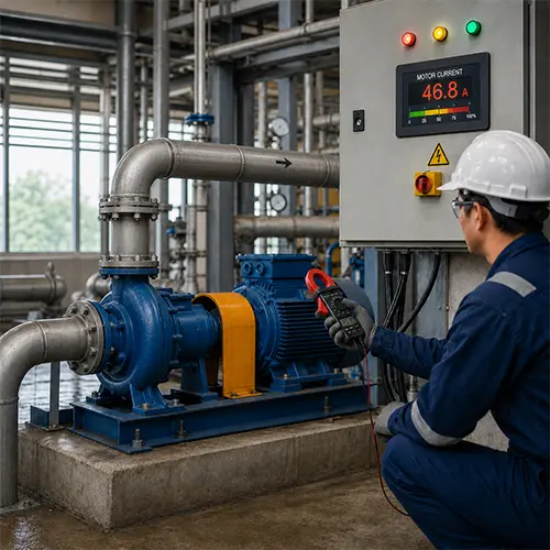
Pump overloads at full flow when the pump requires more shaft power than the motor, VFD, or overload protection system can safely support at the actual operating point. For engineers, maintenance teams, contractors, pump buyers, and plant operators, this problem usually appears as high motor current, thermal overload trips, VFD overload alarms, motor overheating, unstable operation, or repeated shutdown when the discharge valve is fully open or system demand becomes high.
Pump overload at full flow is often a hydraulic operating point problem, not just an electrical problem. Many users first suspect a bad motor, weak overload relay, or poor electrical panel, but the real cause may be that the pump is moving more liquid than the selected duty point, running too far to the right side of the pump curve, operating with too little system resistance, using an oversized impeller, running at excessive speed, handling heavier liquid, or working with insufficient motor power margin.
Pump overload at full flow should be diagnosed with measured data before changing components. The safest decision is to measure actual flow, suction pressure, discharge pressure, total dynamic head, motor current, voltage, frequency, pump speed, impeller diameter, liquid density, and protection settings. Only after the actual operating point is clear should the customer decide whether to throttle flow, reduce speed, trim the impeller, correct VFD settings, repair electrical issues, replace the motor, or reselect the pump.
Scope of This Guide: Which Pump Types and Full-Flow Conditions Does This Apply To?
Pump overload at full flow should be evaluated based on pump type, curve shape, motor sizing, and operating conditions. This guide mainly applies to centrifugal pump systems where the pump runs normally at partial flow but overloads, trips, or draws excessive current when the system opens to high flow or full flow.
This guide is most useful for industrial clean-water systems, cooling water systems, irrigation systems, transfer systems, booster systems, and general centrifugal pump applications. It can also help with slurry, submersible, chemical, and VFD-controlled systems, but those applications require additional checks for solids, cable voltage drop, material compatibility, temperature, and safety procedures.
| Pump Type / Application | Can Use This Guide? | What Must Be Adjusted |
| End suction centrifugal pump | Yes | Focus on curve right-side operation, impeller diameter, speed, and motor sizing |
| Split case pump | Yes | Add large-flow system resistance, valve position, and motor load checks |
| Multistage pump | Yes | Add stage count, pressure, NPSH, and motor power margin checks |
| Pipeline / inline pump | Yes | Add system curve, valve opening, and VFD control checks |
| Booster pump | Yes | Add pressure sensor, VFD frequency, pressure tank, and demand variation checks |
| Irrigation pump | Yes | Add water level, suction lift, pipe friction, and seasonal operation checks |
| Slurry pump | With adjustment | Add solids density, slurry concentration, impeller wear, and torque load |
| Submersible pump | With adjustment | Add cable voltage drop, water level, cooling, and motor protection |
| Positive displacement pump | Partially | Overload logic differs; check relief valve, pressure, viscosity, and speed |
| Fire pump | Limited | Must follow fire pump test procedures, certified curve, and applicable codes |
This guide is not suitable for direct use in fire pump acceptance testing, hazardous chemical transfer, API process pump systems, boiler feed applications, high-temperature liquid systems, positive displacement metering pumps, high-voltage submersible pumps, or warranty disputes without current, flow, head, and curve data. Those cases should follow the pump manual, project specification, applicable code, and qualified engineering procedure.
Why a Pump Overloads at Full Flow
Pump overloads at full flow when the operating point moves too far to the right side of the pump curve and the pump demands more shaft power than the motor can safely deliver. Common causes include too much flow, low system resistance, oversized impeller, high speed, high liquid density, incorrect motor sizing, wrong VFD settings, incorrect overload protection settings, or a pump selected too close to the motor power limit.
A centrifugal pump often draws more power as flow increases. If the system allows the pump to run beyond its intended duty point, the motor may overload even though the pump is not mechanically damaged. The correct diagnosis should compare actual flow, head, current, voltage, speed, impeller diameter, liquid density, pump curve, motor power, service factor, and overload protection settings.
Direct Answer for Fast Diagnosis
Pump overload at full flow is usually caused by the pump operating beyond the selected duty point, not simply by a bad motor. If the pump runs normally at throttled flow but trips when the discharge valve is fully open, check whether the system resistance is too low, the flow is too high, the impeller is too large, the VFD speed is too high, or the motor was selected without enough power margin.
Pump overload at full flow should be checked in this order: confirm actual motor current, measure flow and head, plot the operating point on the pump curve, verify motor power and service factor, check VFD frequency, confirm impeller diameter, review liquid density and viscosity, inspect electrical supply, and then decide whether to limit flow, reduce speed, trim the impeller, correct settings, change the motor, or reselect the pump.
What Does Pump Overload at Full Flow Mean?
Pump overload at full flow means the pump motor draws excessive current when the pump operates at or near the highest flow allowed by the system. In centrifugal pump systems, this often happens because high flow increases shaft power demand, especially when the pump runs too far right on the pump curve.
Full-flow overload does not always mean the motor is defective. It may mean the pump is operating outside its intended hydraulic range. The real question is not only “Why is the current high?” but “Where is the pump operating on the curve, and was the motor selected for that operating point?”
Quick Answer: What Causes Pump Overload at Full Flow?
Pump overload at full flow usually happens because the pump is moving more liquid than intended, the motor power margin is insufficient, or the actual liquid condition is heavier than the pump selection assumed. The key is to determine whether the overload is hydraulic, electrical, mechanical, control-related, or selection-related.
A pump that trips only at full flow is often operating outside the expected duty range. If the discharge valve is fully open and the system resistance is low, the pump may move to the far-right side of the curve. In that region, some centrifugal pumps require higher shaft power, higher NPSH, and more stable suction conditions. If the motor was selected only for the normal duty point, it may not have enough margin for this high-flow condition.
| Field Symptom | Likely Cause | What to Check First | Best Action |
| Motor trips only when valve fully opens | Flow exceeds selected duty point | Flow, head, pump curve | Limit flow or reselect pump |
| Current rises as flow increases | Normal centrifugal pump power behavior | Current vs flow data | Confirm motor margin |
| Pump overloads after impeller replacement | Impeller diameter too large | Impeller trim, curve | Correct impeller diameter |
| Pump overloads after VFD change | Frequency too high | VFD Hz, motor current | Limit max frequency |
| Pump overloads with new liquid | Density or viscosity increased | Liquid SG / viscosity | Recalculate motor power |
| Pump runs hot and vibrates | Operating far from BEP | Flow, vibration, curve | Move operation closer to BEP |
| Protection trips but current is normal | Wrong overload setting | Relay/VFD setting | Correct protection setting |
| Current imbalance between phases | Electrical supply issue | Voltage and phase current | Check power supply and motor |
First Decision: Is the Pump Really Overloaded or Is the Protection Setting Wrong?
Pump overload should not be confirmed until actual motor current, voltage, power, protection settings, and operating conditions are measured. Sometimes the pump is truly overloaded; sometimes the overload relay, VFD, current transformer, or protection threshold is incorrectly set.
Pump overload means the motor or drive system is being asked to deliver more current or power than it can safely handle. It does not automatically mean the pump is broken. It may mean the pump is operating at a flow point where shaft power demand is too high, or it may mean the protection device is set incorrectly.
What “Pump Overload” Actually Means
Pump overload means the load on the motor exceeds the safe operating limit of the motor, VFD, starter, or protection device. In the field, this may appear as motor current above nameplate current, thermal overload trip, VFD overload alarm, motor temperature rise, cable heating, or repeated shutdown during high-flow operation.
Pump overload must be separated from nuisance tripping. If actual current is below the motor rated current but the protection still trips, the issue may be overload relay setting, VFD motor data, current transformer ratio, acceleration time, ambient temperature correction, or wiring error.
Motor Overload vs Hydraulic Overload vs Protection Nuisance Trip
Pump overload diagnosis becomes clearer when the team separates three different conditions: true motor overload, hydraulic overload, and nuisance protection trip. These conditions can look similar in the control panel, but the correct fix is different.
| Condition | What It Means | Field Clue | Best Decision |
| True motor overload | Motor current exceeds safe rating | Current above nameplate, motor heating | Reduce load or resize motor after verification |
| Hydraulic overload | Pump requires too much power at operating point | Flow too high, head low, pump far right on curve | Correct operating point, speed, impeller, or selection |
| Protection nuisance trip | Protection trips although current is acceptable | Current normal but relay/VFD trips | Correct overload relay, CT ratio, VFD motor data, or trip curve |
| Electrical supply overload symptom | Current rises because power supply is poor | Low voltage, phase imbalance, cable heating | Fix supply, cable, contactor, or wiring |
| Mechanical overload symptom | Friction adds extra load | Vibration, bearing heat, rubbing noise | Inspect bearings, seals, impeller, alignment |
A pump should not be fixed by raising the overload setting until actual current proves the trip is not a real overload. Protection devices are there to prevent motor damage, not to be used as a performance adjustment tool.
Check Current Against Motor Nameplate
Pump motor current should be compared with the motor nameplate, not only with the control panel display. Record rated current, actual current on each phase, voltage, frequency, motor power, service factor, and phase imbalance.
If the motor current exceeds the nameplate rating only when the valve is fully open, the overload is probably related to high-flow operation. If one phase is much higher than the others, the issue may be electrical imbalance rather than pump hydraulic load alone.
When Protection Trips but the Motor Is Not Actually Overloaded
Pump protection may trip even when the motor is not overloaded if the overload relay is set too low, the VFD motor nameplate data is wrong, the current transformer ratio is incorrect, or the overload curve does not match the motor and application.
Before increasing any protection setting, confirm the motor nameplate current, measure actual current with a clamp meter, verify voltage, and check whether the motor temperature is normal. Raising protection settings blindly can damage the motor insulation.
| Data Needed | Why It Matters |
| Actual flow | Confirms whether flow is beyond duty point |
| Suction/discharge pressure | Calculates actual head |
| Motor current | Confirms overload |
| Voltage | Detects electrical supply issue |
| Frequency / RPM | Confirms speed |
| Pump curve | Shows expected power |
| Motor nameplate | Confirms rating and service factor |
| Liquid SG / viscosity | Confirms load correction |
Operating Range: BEP, POR, AOR, and Why Full Flow Is Not Always Continuous Duty
Pump overload at full flow is often related to operating range, not only motor size. A pump may be able to produce high flow for a short period, but that does not mean the highest possible flow is the best or safest continuous operating condition.
A professional pump decision should distinguish between BEP, POR, AOR, minimum flow, and maximum recommended flow. These terms help customers understand why “full flow” is not automatically the correct operating target.
What BEP Means
BEP (Best Efficiency Point) is the point on the pump curve where the pump operates with the best hydraulic efficiency and usually the most stable load distribution. A pump does not have to run exactly at BEP all the time, but operation far away from BEP increases the risk of vibration, efficiency loss, bearing load, seal stress, and unstable flow.
When a pump overloads at full flow, check whether the operating point is far to the right of BEP. If it is, the pump may be delivering more flow than the system actually should demand.
What POR Means
POR (Preferred Operating Region) is the flow range where the pump is generally expected to run more efficiently and reliably. Operating within POR helps reduce the risk of vibration, cavitation, high radial load, and overheating.
For many industrial users, POR is more important than theoretical maximum flow. A pump that can physically reach full flow may still be a poor long-term choice if that point is outside the preferred range.
What AOR Means
AOR (Allowable Operating Region) is the wider flow range where the pump may be allowed to operate, often with more restrictions than POR. Operation inside AOR may be acceptable for limited conditions, but it may not be ideal for continuous duty.
A pump overloaded at full flow may be operating near or beyond the right-side boundary of AOR. In that case, using a larger motor does not automatically solve the reliability risk.
Why Full Flow May Not Be Suitable for Continuous Operation
Full flow may not be suitable for continuous operation when motor current exceeds rated current, NPSH margin becomes too small, vibration increases, cavitation noise appears, bearing temperature rises, seal leakage begins, or the pump is operating beyond the recommended curve range.
| Operating Term | Meaning | Customer Decision |
| BEP | Best efficiency and usually best hydraulic balance | Ideal reference point for stable operation |
| POR | Preferred operating range | Best target range for continuous duty |
| AOR | Allowable operating range | May be acceptable with limits |
| Minimum continuous stable flow | Lowest safe continuous flow | Avoid overheating, recirculation, instability |
| Maximum recommended flow | Highest recommended operating flow | Avoid overload, cavitation, and right-curve operation |
| Full system flow | Highest flow allowed by site conditions | Must be verified against curve and motor load |
The practical rule is simple: do not assume the pump should run continuously at the maximum flow the system allows. The acceptable flow range must be confirmed with the pump curve, power curve, motor rating, NPSH margin, and vibration behavior.
Pump Curve and Power Curve: Why Full Flow Can Overload a Centrifugal Pump
Pump overload at full flow often comes from the pump curve and power curve. A centrifugal pump does not draw the same power at every operating point. In many pump designs, shaft power increases as flow increases, especially when the pump moves far to the right side of the curve.
Pump curve analysis is the professional way to diagnose full-flow overload. The pump curve shows how flow, head, efficiency, power, and NPSHr (Net Positive Suction Head Required) change across the operating range. If the measured operating point is not close to the selected duty point, the motor load can be very different from what the buyer expected.
What the Pump Curve Shows
A pump curve shows the relationship between flow and head. It usually also includes efficiency, power, and NPSHr. The duty point is the expected operating point where the pump should deliver the required flow at the required head.
A pump should not be selected only by one flow/head point without checking the full operating range. If the system can run at much higher flow than the selected duty point, the motor may need to support that higher-flow condition.
What the Power Curve Shows
The power curve shows how much shaft power the pump requires at different flow rates. Customers often check the head curve but ignore the power curve. That is a common cause of full-flow overload.
If the motor was selected based only on the design point, but the actual system allows higher flow, the motor may be too small for the maximum operating range. This is especially risky when the pump is installed in a system with lower-than-expected resistance.
Why Full Flow Is Not Always Safe Flow
Full flow is not always safe flow because the maximum flow point may be outside the recommended operating range. Running too far beyond BEP can increase current, vibration, NPSH demand, cavitation risk, bearing load, and seal stress.
If the pump loses efficiency or consumes more power at a high-flow operating point, this pump efficiency loss guide can help engineers check whether the pump is operating away from its best efficiency point.
Why Throttling the Discharge Valve Can Reduce Load in Many Centrifugal Pumps
Throttling the discharge valve can reduce load in many centrifugal pumps because it increases system resistance and reduces flow. When flow decreases, shaft power often decreases for many radial-flow centrifugal pump designs.
This rule should not be applied blindly to every pump. Positive displacement pumps are different; throttling the discharge of a positive displacement pump can create dangerous pressure rise unless a relief valve is correctly installed. Always confirm pump type before using valve control as a load-reduction method.
When NOT to Use Throttling as a Fix
Throttling can be a useful temporary or controlled method for many centrifugal pump systems, but it is not always the correct or safe fix. Customers should not treat valve throttling as a universal solution for every pump overload problem.
The right decision depends on pump type, liquid type, temperature, minimum flow requirement, safety risk, and whether the root cause is excessive flow or another problem such as mechanical friction, VFD overspeed, or electrical supply failure.
Do Not Throttle Positive Displacement Pumps Without Proper Relief Protection
Positive displacement pumps should not be controlled by simply closing or throttling the discharge valve. These pumps can continue pushing liquid and rapidly build dangerous pressure if flow is blocked.
For positive displacement pumps, check the relief valve, pressure limit, speed, viscosity, and system design instead of using discharge throttling as a quick fix.
Do Not Use Throttling to Hide Mechanical Failure
Throttling should not be used to hide bearing damage, seal friction, impeller rubbing, or coupling misalignment. If current is high together with vibration, bearing heat, rubbing noise, or mechanical resistance, the mechanical problem must be repaired.
Reducing flow may temporarily lower current, but it will not correct the damaged component.
Do Not Throttle Slurry Pumps Without Checking Settling Risk
Slurry pumps require careful velocity management. Excessive throttling may reduce velocity and allow solids to settle in the pipeline, causing blockage, wear concentration, or unstable operation.
For slurry systems, consult the pump and pipeline design before using throttling as a long-term correction.
Do Not Throttle Chemical or Hot-Liquid Systems Without Safety Review
Chemical and hot-liquid systems may create heat, vapor pressure, seal, and material safety risks when throttled incorrectly. Some liquids may become more dangerous if temperature rises or pressure changes.
For chemical pumps, check material compatibility, seal system, minimum flow, temperature rise, and site safety procedure before changing valve position.
Do Not Use Throttling Instead of Correct Pump Selection
Throttling is sometimes acceptable for control, but it is not a substitute for correct pump selection. If the pump is consistently too large or operates far from the recommended range, long-term correction may require speed reduction, impeller trimming, system redesign, or pump reselection.
Low System Resistance: The Hidden Reason Pumps Overload at Full Flow
Low system resistance can make a pump deliver more flow than expected, pushing the pump to the right side of the curve and increasing motor load. This often happens when valves are fully open, pipe friction is lower than assumed, discharge head is lower than expected, or bypass lines reduce resistance.
Low resistance sounds beneficial, but it can be risky for centrifugal pumps. A pump selected for a certain head may run at excessive flow if the actual head is lower. In that case, the pump may overload even though the piping seems “easy” for flow.
Why Too Little Head Can Cause Too Much Flow
Too little head can cause too much flow because a centrifugal pump naturally moves to the point where its curve meets the system curve. If the system curve is lower than expected, the intersection point moves to higher flow.
This explains why a pump may run normally when the valve is partially closed but overload when the valve is fully open. The valve adds resistance. When that resistance is removed, the pump may exceed the selected flow range.
Common System Conditions That Reduce Resistance
Low system resistance may be caused by a fully open discharge valve, open bypass line, lower discharge elevation than expected, shorter pipeline than the design assumption, oversized discharge pipe, removed filter, bypassed check valve, low tank pressure, open discharge to atmosphere, or incomplete system backpressure.
If a pump overloads after a piping change, valve replacement, filter removal, or system expansion, the system curve should be recalculated.
How to Confirm Low System Resistance
Low system resistance can be confirmed by measuring actual flow, suction pressure, discharge pressure, and total dynamic head. If the measured head is lower than expected and the measured flow is higher than design, the pump is likely running too far right on the curve.
The customer should also record valve position, pipe route, elevation difference, bypass lines, filter condition, and tank pressure. These details help the supplier determine whether the pump selection or system condition is the root cause.
Impeller Diameter, Speed, and VFD Settings
Pump overload at full flow can occur when the impeller diameter is too large, the pump speed is too high, or the VFD allows the pump to run above the intended frequency. Small changes in speed or impeller size can significantly increase power demand.
These causes are common after pump repair, impeller replacement, VFD commissioning, motor replacement, or frequency conversion from 50 Hz to 60 Hz systems. Even if the pump model is correct, the actual configuration may not match the duty condition.
Oversized or Untrimmed Impeller
An oversized or untrimmed impeller can make the pump require more power than expected. If a pump was supposed to be supplied with a trimmed impeller but received a full-diameter impeller, the pump may overload at high flow.
Impeller diameter should be checked against the pump curve, order confirmation, and nameplate. Do not assume the impeller is correct just because the pump model is correct.
Speed Increase from VFD or Frequency Difference
Speed increase can quickly create overload. A pump originally selected for 50 Hz operation may overload if it is operated near 60 Hz without recalculating flow, head, and power. A VFD (Variable Frequency Drive, a speed-control device for motors) can also cause overload if the maximum frequency is set too high.
The VFD display should be checked during overload. If the pump is running above the intended frequency, the pump may be operating beyond the selected curve.
Affinity Laws in Simple Terms
Affinity laws explain why speed changes are powerful. Flow changes roughly in proportion to speed, head changes roughly with the square of speed, and power changes roughly with the cube of speed.
For example, a small increase in speed can create a much larger increase in power demand. This is why overspeed or wrong frequency settings can turn a normal pump into an overloaded pump.
What to Check in the VFD
VFD settings should be reviewed when pump overload happens at full flow or high demand. Check maximum frequency, motor rated current, acceleration time, current limit, overload curve, PID settings, sensor feedback, sleep/wake logic, and whether the VFD is using the correct motor nameplate data.
If the pump overloads only when the VFD increases speed to meet demand, the issue may be speed limit, system demand, pump selection, or motor sizing.
Liquid Density, Viscosity, and Solids: When the Fluid Is Heavier Than Expected
Pump overload at full flow can happen when the actual liquid is heavier, thicker, hotter, or contains more solids than the pump selection assumed. A pump selected for clean water may overload when handling slurry, glycol mixtures, wastewater, chemical liquids, or high-density process fluids.
Liquid properties matter because pump power depends not only on flow and head, but also on fluid density and hydraulic efficiency. If the selection assumed clean water with SG (Specific Gravity, density relative to water) around 1.0, but the actual liquid has higher SG or viscosity, the motor load may increase.
Specific Gravity Changes Motor Load
Specific gravity directly affects power demand. If the liquid is heavier than water, the pump requires more power for the same flow and head. A motor that is acceptable for clean water may overload with saltwater, chemical solutions, or slurry.
Customers should provide actual SG during selection. If the liquid changes after installation, motor power should be recalculated.
Viscosity Can Reduce Efficiency and Increase Load
Viscosity (resistance to flow) can reduce centrifugal pump performance and change power demand. Higher viscosity often reduces efficiency, shifts the operating point, and may increase load or cause the pump to operate outside the expected curve.
If the pump handles oil, glycol, polymer solution, sludge, or process liquid, do not rely only on a clean-water pump curve.
Solids and Slurry Can Cause Full-Flow Overload
Solids and slurry can increase load through density, friction, blockage, and wear. A slurry pump may require a different motor margin, impeller design, and speed limit than a clean-water pump.
If full-flow overload appears together with vibration, flow instability, or rapid wear, solids concentration and impeller condition should be checked.
| Liquid Factor | What to Check | Why It Matters |
| Specific gravity | Actual SG | Corrects power demand |
| Viscosity | cP or equivalent | Changes pump performance |
| Temperature | Operating temperature | Affects viscosity and NPSH |
| Solids content | % by weight/volume | Adds load and wear |
| Chemical compatibility | Material and seal match | Prevents failure |
| Gas content | Entrained air | Causes instability and false readings |
Motor Sizing and Service Factor: Was the Motor Selected Too Close to the Limit?
Pump overload at full flow can occur if the motor was selected only for the design duty point without enough margin for high-flow operation, liquid changes, voltage variation, or curve tolerance. Motor sizing should be checked against the maximum expected load, not only the normal duty point.
Motor sizing is a decision issue, not just a component issue. A motor may be correct for one operating point but insufficient for another. If the pump can run at a higher-flow point, the motor must be able to handle that condition or the system must limit the pump from reaching it.
Why Design Point Power Is Not Enough
Design point power is not enough if the system can operate outside the design point. The motor must be checked against the power curve across the actual operating range.
If the pump is used in a system with variable demand, open discharge, changing tank levels, or different valve positions, the maximum expected load may occur away from the normal duty point.
What Motor Service Factor Means
Service factor is a limited safety margin, not a license for continuous overload. Some users assume they can operate above rated power because the motor has a service factor, but that can shorten motor life, especially in hot environments or poor ventilation.
A pump should not rely on service factor as its normal operating condition. Continuous operation should stay within the motor’s rated capacity unless the motor manufacturer and application conditions allow otherwise.
When a Larger Motor Is the Correct Fix
A larger motor may be the correct fix when the pump selection, operating point, speed, impeller diameter, liquid condition, and system curve are all correct, but the motor was selected too close to the load requirement.
In this case, upgrading the motor may provide the needed power margin. However, electrical cables, starter, VFD, base, coupling, and protection settings must also be checked.
When a Larger Motor Is the Wrong Fix
A larger motor is the wrong fix if the pump is overloading because it is operating too far right on the curve, cavitating, vibrating, or running outside the recommended operating range. A larger motor may allow the pump to keep running in a harmful condition, leading to seal failure, bearing failure, impeller damage, or excessive energy consumption.
The operating point should be corrected before motor upgrade is considered.
Electrical Causes That Make Pump Motor Current Too High at Full Flow
Electrical supply problems can make a pump appear overloaded even when hydraulic load is not the only issue. Low voltage, phase imbalance, wrong motor connection, poor cable sizing, and incorrect overload settings can all cause high current, heat, or nuisance trips.
Electrical checks should always be part of overload diagnosis. A pump may be hydraulically acceptable but still trip because the motor is not receiving proper power.
Low Voltage Increases Current
Low voltage can increase motor current and heat. When voltage is low, the motor may struggle to deliver torque, especially under full-flow load. This can lead to overload trips and motor heating.
Voltage should be measured at the motor terminals while the pump is running under load, not only at the control panel with the pump stopped.
Phase Imbalance
Phase imbalance can cause one phase to carry higher current than the others. Even small voltage imbalance can create larger current imbalance and extra heat in the motor.
If the pump overloads at full flow and one phase current is much higher, check supply quality, cable connections, contactor condition, and motor winding condition.
Incorrect Motor Wiring
Incorrect motor wiring can cause high current, low torque, poor performance, or overheating. Star-delta wiring mistakes, wrong voltage connection, incorrect frequency assumptions, or mismatched motor nameplate data can all create overload-like symptoms.
Wiring should be verified by qualified personnel before repeated operation.
Cable Voltage Drop
Cable voltage drop can become important for long cable runs, especially in submersible pumps, remote pump stations, and irrigation systems. If the cable is undersized or connections are poor, voltage at the motor may be lower than expected.
Cable size, cable length, joint condition, and terminal temperature should be inspected when overload appears under high load.
Mechanical Causes That Increase Load at Full Flow
Mechanical problems can increase running load and make full-flow overload worse. Bearing damage, seal friction, impeller rubbing, coupling misalignment, pipe stress, or internal wear can add mechanical resistance on top of hydraulic load.
Mechanical load is often overlooked because the overload appears only at high flow. However, a pump already near the motor limit may trip when mechanical friction adds extra torque demand.
Bearing or Seal Friction
Bearing damage, poor lubrication, or excessive seal friction can increase load and temperature. If overload is accompanied by bearing noise, rising bearing temperature, or shaft resistance, mechanical inspection is needed.
A pump with mechanical friction may overload even if the hydraulic operating point appears acceptable.
Impeller Rubbing or Internal Contact
Impeller rubbing can occur due to wear ring issues, casing distortion, bearing movement, assembly error, or pipe stress. Internal contact increases current, vibration, and heat.
If the pump was recently repaired, impeller clearance and internal assembly should be checked.
Coupling Misalignment
Coupling misalignment increases mechanical load, bearing stress, vibration, and heat. It may not be the only cause of overload, but it can push a marginal system into trip condition.
If high current appears together with vibration, coupling heat, or bearing temperature rise, this pump shaft misalignment guide can help maintenance teams check whether alignment or pipe stress is adding mechanical load.
Cavitation, Air, and Unstable Flow at High Flow
Pump overload at full flow can be confused with cavitation or air-related instability. At high flow, suction demand increases, NPSHr rises, and the pump may experience cavitation, vibration, noise, fluctuating current, or unstable discharge.
Full-flow operation can expose suction-side weaknesses that are not visible at partial flow. If the pump becomes noisy, unstable, or vibrates at high flow, the issue may not be pure overload. It may be cavitation, air entry, suction restriction, or unstable system operation.
Why High Flow Increases NPSH Requirement
High flow increases NPSHr because inlet velocity and losses increase. If NPSHa (Net Positive Suction Head Available) is not enough, the pump may cavitate.
Cavitation can cause noise, vibration, impeller erosion, unstable flow, and fluctuating current. It can also reduce pump efficiency, which may increase the stress on the motor and system.
Air in the Pump Can Distort Readings
Air in the pump can create unstable pressure, unstable flow, and fluctuating current. Operators may mistake these symptoms for electrical overload or pump failure.
If full-flow operation causes air bubbles, unstable pressure, or repeated priming issues, this <a href=”https://liqenpower.com/why-air-inside-pump/”>air inside pump troubleshooting guide</a> can help identify suction leaks, air lock, and cavitation risk.
How to Separate Overload from Cavitation
Overload usually shows a consistent current increase with flow. Cavitation often shows noise, vibration, unstable pressure, and possible flow loss. Air-related problems often show bubbles, pressure fluctuation, and priming instability.
To separate them, record current, flow, suction pressure, discharge pressure, vibration, noise pattern, and whether symptoms improve when flow is reduced.
Full-Flow Acceptance Test Checklist
A full-flow acceptance test helps confirm whether the pump can safely operate at the site’s high-flow condition. This checklist is useful for commissioning, troubleshooting, supplier communication, and internal maintenance reports.
The goal is not only to prove whether the pump can deliver flow. The goal is to prove whether the pump can deliver that flow safely, with acceptable current, voltage, temperature, vibration, suction condition, and operating range.
| Acceptance Item | Design / Required Value | Measured Value | Pass / Fail | Decision |
| Flow rate | Required duty or maximum expected flow | Confirm if flow exceeds design | ||
| Total Dynamic Head | Design TDH | Confirm operating point | ||
| Motor current | Nameplate rated current | Check overload margin | ||
| Voltage at motor | Rated voltage range | Check supply quality | ||
| Phase current balance | Balanced phases | Check electrical imbalance | ||
| VFD frequency / RPM | Design speed | Confirm no overspeed | ||
| Discharge pressure | Expected operating pressure | Check system resistance | ||
| Suction pressure | Required suction condition | Check NPSH risk | ||
| Motor temperature | Acceptable operating range | Confirm heat risk | ||
| Bearing temperature | Acceptable operating range | Check mechanical friction | ||
| Vibration | Site or project limit | Check reliability risk | ||
| Valve position | Required operating position | Record system condition | ||
| Liquid SG / viscosity | Selection assumption | Recalculate power if different | ||
| Alarm record | No overload / fault alarm | Confirm control stability |
A pump should not be approved for continuous full-flow operation only because it “does not trip once.” The test should confirm stable operation after warm-up, acceptable current, acceptable temperature, stable suction, and acceptable vibration.
Step-by-Step Troubleshooting When a Pump Overloads at Full Flow
Pump overload at full flow should be diagnosed in a fixed sequence: confirm real overload, measure operating point, compare the pump curve, check system resistance, verify speed and impeller size, review liquid properties, inspect electrical supply, and then decide whether to adjust, repair, resize, or reselect.
This sequence prevents random decisions. Replacing the motor, increasing overload settings, or changing pumps before measuring the operating point can waste money and leave the real cause unresolved.
Step 1: Confirm the Overload Is Real
First confirm actual current, motor rated current, overload setting, VFD alarm code, and motor temperature. Measure each phase current if it is a three-phase motor.
If current is normal but protection trips, correct protection settings before changing the pump.
Step 2: Measure Actual Flow and Head
Next measure actual flow and suction/discharge pressure. Use these values to calculate actual total dynamic head.
Valve position alone does not define full flow. The pump’s real operating point must be measured.
Step 3: Plot the Operating Point on the Pump Curve
Plot actual flow and head on the pump curve. Check whether the pump is near the selected duty point, near BEP, or too far right on the curve.
If the pump is operating far beyond the recommended flow range, reduce flow, reduce speed, trim impeller, or reselect the pump.
Step 4: Check VFD Frequency and Pump Speed
Check actual frequency or RPM. If the VFD is running above the intended frequency, the pump may overload because speed increases power demand sharply.
Correct maximum frequency, PID control, acceleration time, and current limit settings as needed.
Step 5: Confirm Impeller Diameter and Stage Configuration
Confirm impeller diameter, impeller trim, stage count, and pump model. A wrong impeller or stage configuration can create higher power demand than expected.
Compare the supplied configuration with the pump curve and order confirmation.
Step 6: Check Liquid Density, Viscosity, and Solids
Check whether the actual liquid matches the selection assumption. Higher SG, higher viscosity, solids, or temperature changes can affect motor power.
If the liquid is not clean water, recalculate power demand.
Step 7: Check Electrical Supply
Measure voltage under load, phase balance, cable voltage drop, motor wiring, and protection settings. Electrical problems can cause high current even when the hydraulic load is acceptable.
Correct electrical issues before changing the pump.
Step 8: Inspect Mechanical Load
Inspect bearings, seals, impeller clearance, coupling alignment, pipe stress, and internal rubbing. Mechanical friction can push current above the safe limit.
If overload appears with vibration or heat, mechanical inspection is essential.
Step 9: Decide the Correct Fix
Choose the fix based on evidence. If flow is too high, limit flow or reduce speed. If the impeller is too large, trim or replace it. If the motor is undersized for correct operation, upgrade the motor. If liquid is heavier than expected, recalculate selection. If the pump is outside the recommended range, reselect the pump.
If the pump trips at full flow and the actual discharge becomes unstable, this pump flow drop troubleshooting guide can help operators separate flow restriction, suction shortage, discharge blockage, and system curve problems.
Full-Flow Overload Decision Framework
The correct fix depends on whether pump overload is caused by excess flow, low system resistance, wrong speed, oversized impeller, heavier liquid, undersized motor, electrical supply issues, or mechanical friction. The decision should be based on measured data, not guesswork.
| Situation | Likely Meaning | Best Decision |
| Current rises only when valve fully opens | Excess flow / low system resistance | Limit flow or adjust operating point |
| Actual flow is higher than design | Pump running too far right | Throttle, trim impeller, reduce speed, or reselect |
| Actual head is much lower than expected | System resistance too low | Add control valve or review system design |
| VFD frequency exceeds design | Speed too high | Limit maximum frequency |
| Impeller is larger than required | Pump power too high | Trim or replace impeller |
| Liquid SG is higher than assumed | Higher shaft power | Recalculate motor power |
| Current high but flow/head normal | Electrical/mechanical issue | Check voltage, phase, bearings, alignment |
| Protection trips but current normal | Setting issue | Correct overload/VFD settings |
| Pump is far from BEP | Reliability risk | Reselect or change operating point |
A larger motor is not always the best decision. If the pump is operating in the wrong hydraulic range, correcting the operating point is usually safer than simply increasing motor power.
Best Fix by Root Cause
The best fix for pump overload at full flow depends on the actual root cause. A repair decision should not be based only on the alarm message because the same overload alarm can come from excess flow, high density liquid, VFD overspeed, electrical problems, or mechanical friction.
| Root Cause | Best Fix | What Not to Do |
| Excess flow | Limit flow, reduce speed, or reselect pump | Do not only raise overload setting |
| Low system resistance | Add proper control resistance or recalculate system curve | Do not assume valve fully open is best |
| Oversized impeller | Trim or replace impeller | Do not immediately replace motor |
| VFD overspeed | Limit maximum frequency | Do not operate beyond selected curve |
| High SG liquid | Recalculate motor power | Do not use clean-water curve blindly |
| Undersized motor | Upgrade motor after verification | Do not oversize without checking pump range |
| Protection setting error | Correct relay/VFD settings | Do not change pump before confirming current |
| Mechanical friction | Repair bearing, seal, impeller, alignment issue | Do not hide friction by throttling only |
| Cavitation or air | Correct suction and priming conditions | Do not treat unstable current as motor-only issue |
This table is useful for internal reporting because it connects the measured cause with the correct decision and the wrong shortcut to avoid.
Cost Consequences of Wrong Full-Flow Overload Decisions
Wrong decisions can turn a manageable overload issue into motor damage, repeated downtime, seal failure, bearing failure, energy waste, or unnecessary pump replacement. The lowest-cost solution is the one that corrects the actual operating point.
Full-flow overload is often expensive because it may look like a simple electrical trip while the real cause is hydraulic mismatch. If the customer only resets the overload device, the motor may fail. If the customer only replaces the motor, the pump may continue to run in a damaging region.
| Wrong Decision | Likely Result | Cost Consequence |
| Replacing motor without checking flow | Pump keeps operating too far right | Higher energy use and pump wear |
| Raising overload setting blindly | Motor runs hotter | Motor insulation damage |
| Fully opening valve to “get more water” | Flow exceeds design | Overload, cavitation, vibration |
| Ignoring liquid density | Motor remains undersized | Repeated trips |
| Ignoring VFD frequency | Pump runs above curve limit | Overload and mechanical stress |
| Replacing pump without system data | Same issue may repeat | Procurement waste |
| Ignoring mechanical friction | Bearing/seal failure worsens | Repair cost increases |
The best economic decision is to identify whether the pump is overloaded because it is doing too much work, because the motor is too small, because the liquid is heavier, or because the electrical/mechanical system is unhealthy.
When the Pump or Supplier Configuration May Be the Real Problem
The pump or supplier configuration may be the real problem if the supplied pump does not match the confirmed duty point, curve, impeller diameter, motor power, speed, stage count, or liquid condition. A fair diagnosis should check both site conditions and supplied configuration.
Supplier responsibility becomes more likely when field data proves the site condition matches the agreed selection basis, but the pump still operates outside the expected curve or overloads under conditions it was supposed to handle.
Configuration Problems That Can Cause Full-Flow Overload
Configuration problems may include wrong impeller diameter, wrong impeller trim, wrong motor power, wrong motor speed, wrong stage count, wrong VFD parameter setting, wrong liquid assumption, supplied curve not matching the actual pump, or misunderstanding of motor service factor.
If the pump overloads from the first commissioning, compare the delivered pump with the approved datasheet, curve, and order confirmation.
When Supplier Inspection Is Reasonable
Supplier inspection is reasonable when actual flow, head, current, voltage, speed, liquid properties, and impeller configuration have been confirmed, but the pump still does not match the expected curve or motor loading.
Inspection is also reasonable if the motor nameplate, impeller trim, stage count, or supplied curve does not match the order.
Supplier Data Checklist
| Data Type | What to Provide | Why It Matters |
| Pump model | Confirms selection | Avoids model confusion |
| Pump curve | Shows expected flow/head/power | Compares operating point |
| Motor nameplate | Confirms power and current | Checks overload margin |
| Actual flow | Confirms full-flow condition | Finds excess flow |
| Suction/discharge pressure | Calculates TDH | Confirms head |
| VFD settings | Confirms speed | Finds overspeed |
| Liquid data | SG / viscosity / solids | Recalculates power |
| Site photos/videos | Shows piping and valves | Finds system issue |
Factory Test vs Site Test: Why Full-Flow Results May Differ
Factory test and site test may differ because factory testing measures pump performance under controlled conditions, while site performance depends on piping, valve position, suction condition, liquid properties, power supply, VFD settings, and operating point.
This distinction matters in overload disputes. A pump may pass factory testing but overload on site if the site allows excessive flow, uses different liquid, has lower system head, runs at higher speed, or uses different control settings.
What Factory Test Can Prove
Factory test can prove that the pump meets expected performance under controlled test conditions. It may confirm flow, head, power, efficiency, vibration, and sometimes NPSH-related behavior at specified points.
Factory testing does not prove that the site piping, valves, liquid, electrical supply, or VFD settings are correct.
What Site Test Can Prove
Site test proves how the pump and system work together. It shows the real operating point, real current, real voltage, real system resistance, real speed, and real overload behavior.
If a pump overloads only on site, the site test should identify whether the actual operating point is different from the selection basis.
How to Compare Factory and Site Results Fairly
Factory and site results should be compared under the same speed, same impeller diameter, same liquid or correction factor, same flow/head reference, correct pressure gauge position, correct current measurement, verified valve position, and verified VFD setting.
If site conditions match the test basis but results still differ significantly, supplier review is justified.
Troubleshooting Tools Checklist
Pump overload at full flow should be diagnosed with measurable data. Without flow, head, current, voltage, speed, and pump curve information, the diagnosis becomes guesswork.
| Tool | What It Checks | Why It Matters |
| Clamp meter | Motor current | Confirms overload |
| Multimeter | Voltage / phase | Detects electrical issues |
| Pressure gauges | Suction and discharge pressure | Calculates head |
| Flow meter | Actual flow | Confirms over-flow condition |
| Tachometer / VFD display | Speed | Confirms RPM or Hz |
| Pump curve | Expected flow/head/power | Finds operating point |
| Liquid data sheet | SG and viscosity | Corrects power demand |
| Vibration meter | Mechanical condition | Finds friction/misalignment |
| Infrared thermometer | Motor/bearing temperature | Detects heat risk |
| System drawing | Piping and valve layout | Checks system resistance |
Get A Quote

Get A Quote
0 Comments