
Slurry Pump NPSH Explained: How to Prevent Cavitation in Abrasive Pumping Systems
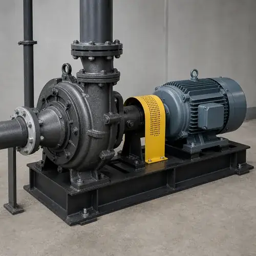
If you're specifying or troubleshooting a slurry pump and seeing premature impeller erosion, noise, or erratic performance, the culprit is often low NPSHa relative to actual slurry conditions. Slurry pump NPSH — the margin between available suction head and what the pump requires — works differently when solids are in the mix. Most pump curves show NPSHr tested on clean water, but slurry is heavier, more turbulent, and far less forgiving. This guide gives you the engineering steps to calculate NPSHa correctly, design suction piping for abrasive service, spot cavitation before it destroys your pump, and verify supplier data so you don't end up with a pump that cavitates from day one.
Slurry pump cavitation isn't just a hydraulic nuisance — it accelerates wear on high-chrome impellers, cracks suction liners, and can eat through a mechanical seal far faster than clean‑water service would suggest. For mining, dredging, and dewatering projects, unscheduled downtime often costs far more than the pump itself. The decisions you make at the system-design and RFQ stage determine whether your pump runs for years or fails prematurely under warranty disputes.
By the end of this article, you'll be able to: estimate your true NPSHa including slurry-induced suction losses, interpret NPSHr curves with a realistic safety margin, identify piping mistakes that cause cavitation, and ask suppliers the right questions before ordering. Let’s break down the basics.
What Is Slurry Pump NPSH and Why Does It Matter?
Net Positive Suction Head in slurry service isn't a new term — it's the same NPSH as any centrifugal pump, but the consequences of getting it wrong are far more expensive. Slurry pump NPSH is the margin of pressure at the pump suction eye that prevents the liquid from flashing into vapor. When that margin disappears, cavitation bubbles form, collapse violently, and with slurry the collapse happens right against abrasive particles. That combination eats metal faster than most design manuals predict.
Engineers who come from clean-water or wastewater backgrounds often under‑estimate NPSH issues in slurry because they assume the same rules apply. They don't. The pump's published NPSHr curve is typically based on a hydraulics lab test with clean water and a 3% head drop threshold. That curve doesn't know about solids settling in the suction line, density-driven friction spikes, or the turbulence that eats away available suction energy long before a vacuum gauge registers it.
NPSHa vs NPSHr in Abrasive Pumping Systems
The physics is the same everywhere: NPSHa (available) must exceed NPSHr (required) by a safe margin. The difference in slurry is how fast NPSHa can drop once solids concentration changes, and how poorly the published NPSHr reflects real cavitation inception in dense, two-phase flows. Under the Hydraulic Institute's ANSI/HI 9.6.1 guidance, a clean-water centrifugal pump might run reliably with NPSHa just 0.5–1 m above NPSHr. For an abrasive slurry pump, experienced system designers demand at least 2 m of margin — often more if the solids concentration varies hour by hour, or if the suction arrangement includes long horizontal runs or lift conditions.
| Factor | Clean Water | Slurry |
|---|---|---|
| NPSHr test medium | Water | Water only (no industry slurry test standard) |
| Typical safety margin (NPSHa – NPSHr) | 0.5–1.5 m | 2–4 m (site-dependent) |
| Suction friction loss | Based on water viscosity | Can increase 10–30% or more, depending on density and settling |
| Cavitation inception | Near published NPSHr | Often begins well above published NPSHr |
| Damage mechanism | Pitting, vibration | Pitting + particle impact accelerates wear 3–5× |
That table alone should make you re‑think a selection based on marginal clean‑water data. If your supplier can't confirm the safety margin they recommend for your specific slurry, you're already at risk.
Why Slurry Increases Cavitation Risk Compared With Water
The simplest explanation: water carries energy; slurry steals it on the way to the pump. Every increase in solids concentration raises the mixture's density, which directly increases friction losses in the suction pipe — losses that subtract from the NPSHa you calculated using water constants. Then, when cavitation bubbles do form, the collapse isn't just a hydraulic hammer; it's a hammer driving sharp-edged solids into the impeller and liner at a microscopic scale. That's why a slurry pump that cavitates fails significantly faster than a clean-water pump would under similar conditions. For a complete look at how solids size and concentration influence pump selection, see our slurry pump selection guide.
How Solids and Density Affect Suction Head Loss
Let’s be specific. A slurry mixture with a specific gravity of 1.3 (density around 1,300 kg/m³, typical for many sand‑water slurries) isn't 30% heavier — it’s about 30% denser. The suction piping friction factor doesn't scale linearly because slurry viscosity and solids settling behavior matter too. Field experience suggests that suction head loss can increase by roughly 15–30% over clean‑water calculations when SG exceeds about 1.2, and the increase may reach 40% or more for slurries with SG above 1.5. These are approximate ranges that depend heavily on particle size, solids settling tendency, pipe roughness, and operating velocity — they should be treated as preliminary engineering estimates, not fixed corrections. Always validate with on‑site suction pressure measurements or request the pump supplier’s specific friction‑loss assessment methodology. That's extra head loss you must subtract from NPSHa, yet many specifiers never adjust their spreadsheet. Worse, if the slurry is non‑Newtonian (certain mineral tailings, for example), the friction loss at low flow can spike even further, eroding the NPSH cushion right when the pump is running at part‑load — which also happens to be where NPSHr often rises.
There's a second density effect that rarely appears in standard pump specifications. While NPSHr is measured in meters of fluid and does not increase directly with density, denser or non-homogeneous slurry can alter the local flow field near the impeller eye. This may shift the point of cavitation inception or reduce the effective safety margin, even when the published NPSHr number appears acceptable under clean‑water assumptions.
Why Abrasive Cavitation Causes Faster Wear
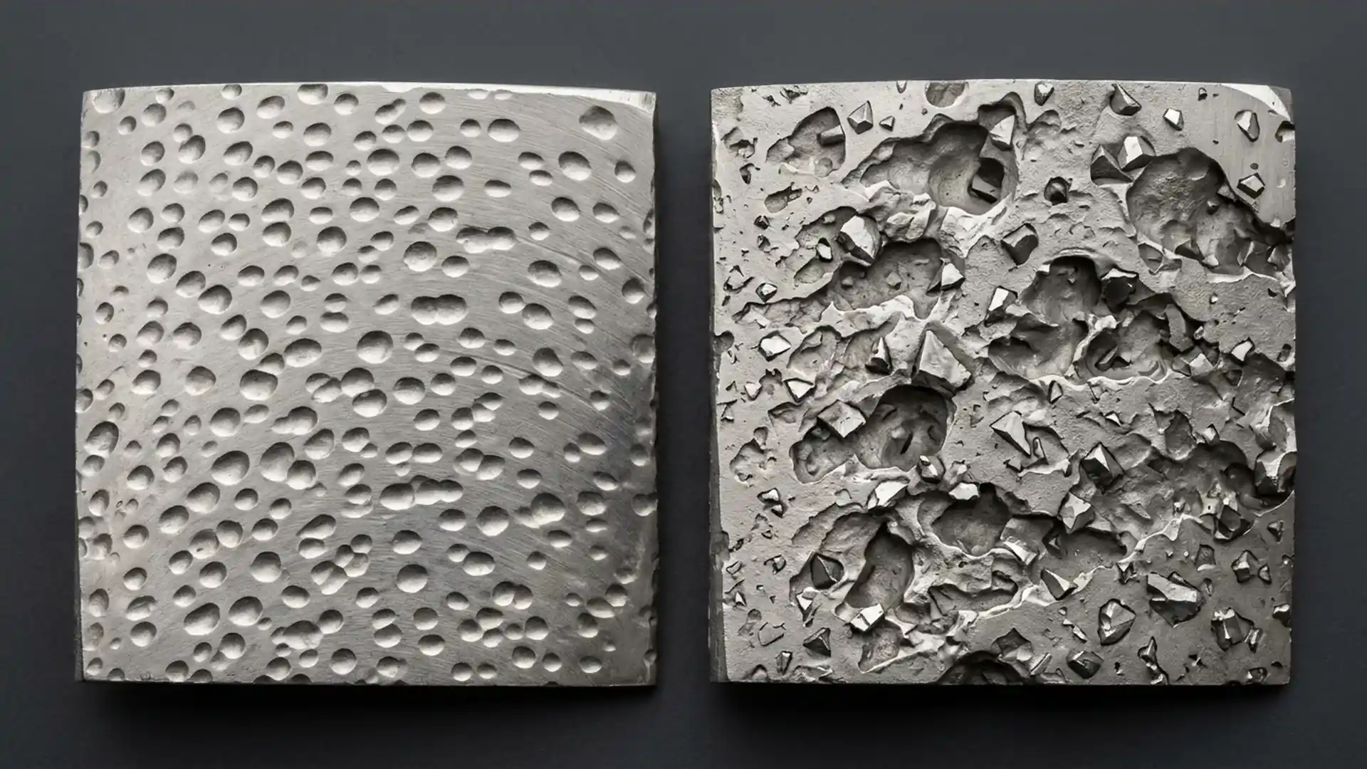
Cavitation damage in clean water progresses by gradual surface fatigue — pits grow, metal flakes off, performance degrades. In slurry, the bubble collapse hurls entrained particles against the surface at impact velocities that exceed normal flow conditions. Picture microscopic sandblasting inside each collapsing bubble cloud. The result is erosion rates that can be three to five times faster than classic cavitation pitting, and the damage pattern often extends further downstream on the impeller vane because the solids carry momentum even after the bubble disappears. That's why maintenance planners who open a slurry pump after 2,000 hours of cavitation see not just pitting but deep gouges across the high‑chrome iron — wear that looks like it ran for a year.
| Slurry Condition | Likely NPSHa Impact | Cavitation Risk |
|---|---|---|
| Low solids % (<10%) | Minor suction loss | Low if suction design is good |
| Medium solids (10–25%) | 10–25% higher friction loss | Moderate, margin below 2 m is risky |
| High solids (25–40%) | Can exceed 20–40% higher friction loss (site‑dependent) | High, needs 3 m margin minimum |
| Dense slurry (SG >1.4) | Friction loss can reach 30–50% above water estimate, confirm by measurement | Very high, flooded suction strongly recommended |
| Variable concentration | Unstable NPSHa | Critical — cavitation surges possible |
| Long suction line (>10 m) | Significant cumulative loss | High, oversize pipe + straight run essential |
| Suction lift (negative static head) | Reduced starting NPSHa | Extreme, avoid if possible |
How to Calculate NPSHa for a Slurry Pump System
You don't need a CFD package. The classic energy equation works, but you must feed it real numbers.
NPSHa = Ha ± Hs – Hf – Hvp
Where:
- Ha: Absolute pressure on the liquid surface (atmospheric pressure minus altitude correction). At sea level, approximately 10.33 m. Subtract about 1.2 m per 1,000 m of altitude.
- Hs: Static head — positive if the liquid level is above the pump centerline, negative if it’s a suction lift.
- Hf: Friction head loss in the suction pipe, valves, and fittings. This is where slurry density kicks in. Calculate Hf for water first using standard pipe friction equations, then apply a density correction factor (typically 1.1–1.5× depending on SG and solids settling behavior).
- Hvp: Vapor pressure of the liquid, in meters of fluid. For water at 20°C it's about 0.24 m; higher temperatures raise it significantly.
The slurry twist: Hf must be adjusted upward. You do not simply plug slurry SG into the friction calculation as if it were a homogeneous Newtonian fluid; you need actual slurry rheology data or at least a conservative multiplier derived from similar sites. Many experienced engineers use a 1.3–1.5× factor on the clean‑water Hf for sand‑type slurries above 15% solids by weight, and confirm with a physical suction pressure test at commissioning.
Step-by-Step NPSHa Calculation Example
Let's walk through a realistic mining dewatering scenario:
- Slurry: fine sand, 20% wt solids, SG 1.25
- Flow: 120 m³/h
- Suction pipe: DN200, 15 m long, one 90° elbow, one gate valve (fully open)
- Static lift: 2 m (pump centerline 2 m above liquid surface)
- Site altitude: 800 m above sea level
- Liquid temperature: 25°C
First, clean‑water Hf: at 120 m³/h in DN200, velocity ≈ 1.06 m/s. Using a typical friction factor and fitting coefficients, we get about 0.8 m total suction head loss for water.
Density correction: with SG 1.25 and settled solids tendency, we apply a 1.4× multiplier — making Hf ≈ 1.12 m.
Altitude correction: Ha ≈ 10.33 – (1.2 × 0.8) = 9.37 m
Vapor pressure: at 25°C, Hvp ≈ 0.32 m
NPSHa = 9.37 – 2.0 – 1.12 – 0.32 = 5.93 m
If the pump's published NPSHr at 120 m³/h is 4.0 m (water), your margin is just 1.93 m — below the recommended 2–3 m for slurry. This system will likely cavitate at the first increase in solids or when the suction strainer starts clogging. The fix? Lower the pump (reduce lift), enlarge the suction pipe, or select a pump with lower NPSHr.
Common Calculation Mistakes in Slurry Systems
I see the same three mistakes on RFQs and site audits:
- Forgetting altitude. At 2,000 m above sea level, Ha drops to about 7.9 m — you've lost 2.4 m of absolute pressure before you even start. Suction lift that worked at sea level becomes impossible.
- Using SG directly in Darcy‑Weisbach. Slurry isn't a simple heavy fluid; pipe friction isn't proportional to SG alone. Applying a straight SG multiplier to friction head without considering solids behavior usually gives an over‑optimistic NPSHa. Talk to your pump supplier about their recommended correction method for your specific slurry.
- Ignoring transient conditions. When a sump level drops, static head drops. When a pipe wears internally, friction rises. Your NPSHa calculation only matters at the worst‑case operating point, not the design point.
Suction Piping Design Recommendations for Slurry Pumps
I’ve seen operators invest in a high‑chrome slurry pump only to connect it with a 3" suction line from a choked sump, then wonder why it cavitates. Suction piping is often the cheapest component, but it makes or breaks NPSHa. A few simple rules eliminate most slurry cavitation problems.
- Eccentric reducer, flat side up. If the suction pipe is larger than the pump suction nozzle, use an eccentric reducer with the flat side on top. A concentric reducer with a vertical suction line traps air; in a slurry line, that air pocket triggers violent cavitation.
- Minimum 5–10 pipe diameters of straight pipe before the pump suction flange. Elbows, tees, or butterfly valves right at the inlet create uneven flow and local pressure drops that eat NPSHa.
- Suction velocity below 1.2 m/s for most abrasive slurries. Lower for coarser solids. This keeps settling minimal and friction losses in check.
- Flooded suction whenever possible. Placing the pump below the liquid level gives you the full static head as a credit — often the single most effective way to boost NPSHa.
- No check valves or foot valves in the suction line unless absolutely necessary. They clog with solids and create a point of unpredictable friction loss.
For a deep dive on pipe sizing and friction loss calculations, see our pump system design guide.
Recommended Suction Velocities and Pipe Layout Practices
| Slurry Type | Max Suction Velocity (m/s) | Minimum Straight Run Before Pump (× pipe dia.) | Reducer Orientation |
|---|---|---|---|
| Fine sand, <15% solids | 1.2–1.5 | 5 | Eccentric, flat side up |
| Medium sand, 15–30% solids | 0.9–1.2 | 7 | Eccentric, flat side up |
| Coarse solids, >5 mm | 0.6–0.9 | 10 | Eccentric, flat side up |
| Dredge slurry, high SG | 0.5–0.8 | 10 | Avoid reducers if possible; line size same as pump nozzle |
When a Larger Suction Pipe Is Worth the Cost
Up‑sizing the suction line by one or two nominal sizes is one of the most cost‑effective anti‑cavitation moves you can make. The pipe cost increase is marginal, yet the friction head reduction is dramatic (proportional to the 5th power of diameter per typical flow‑velocity relationships). In one audit I reviewed, moving from DN150 to DN200 on a 30 m suction run roughly halved the suction loss and increased NPSHa by about 2 m — the difference between persistent cavitation and stable operation. The modest extra cost of the pipe and fittings was quickly recovered through fewer impeller replacements.
Warning Signs of Slurry Pump Cavitation
Even with solid calculations, cavitation can creep in as slurry conditions change. You need to recognize it before the impeller is scrap.
- Gravel‑in‑a‑blender noise. Classic cavitation sound is a crackling or rattling from the suction side. In slurry pumps the noise is often louder and more irregular because solids clatter against the casing.
- Suction pressure gauge oscillating rapidly by more than ±0.3 bar. A steady reading within the pump's margin is one thing; a flickering needle means the suction eye is alternately flooded and starved.
- Discharge pressure and flow instability. If the pump wanders on its curve without a corresponding level change, suspect suction recirculation or vapor formation.
- Vibration at the bearing housing. A constant rumble isn't cavitation; it's typically imbalance or misalignment. Cavitation vibration is erratic, high‑frequency, and grows under higher flow demand.
- Impeller inspection. When you pull the pump, look for pitting concentrated on the suction side of the vanes near the eye, not further out toward the discharge. If the pitting is sharply localized with a "spongy" surface, it's cavitation. If the wear is broadly swept along the vane with directional grooves, it's more likely erosion.
A broader diagnostic flow is available in our pump cavitation troubleshooting guide.
Cavitation Damage vs Normal Abrasive Wear
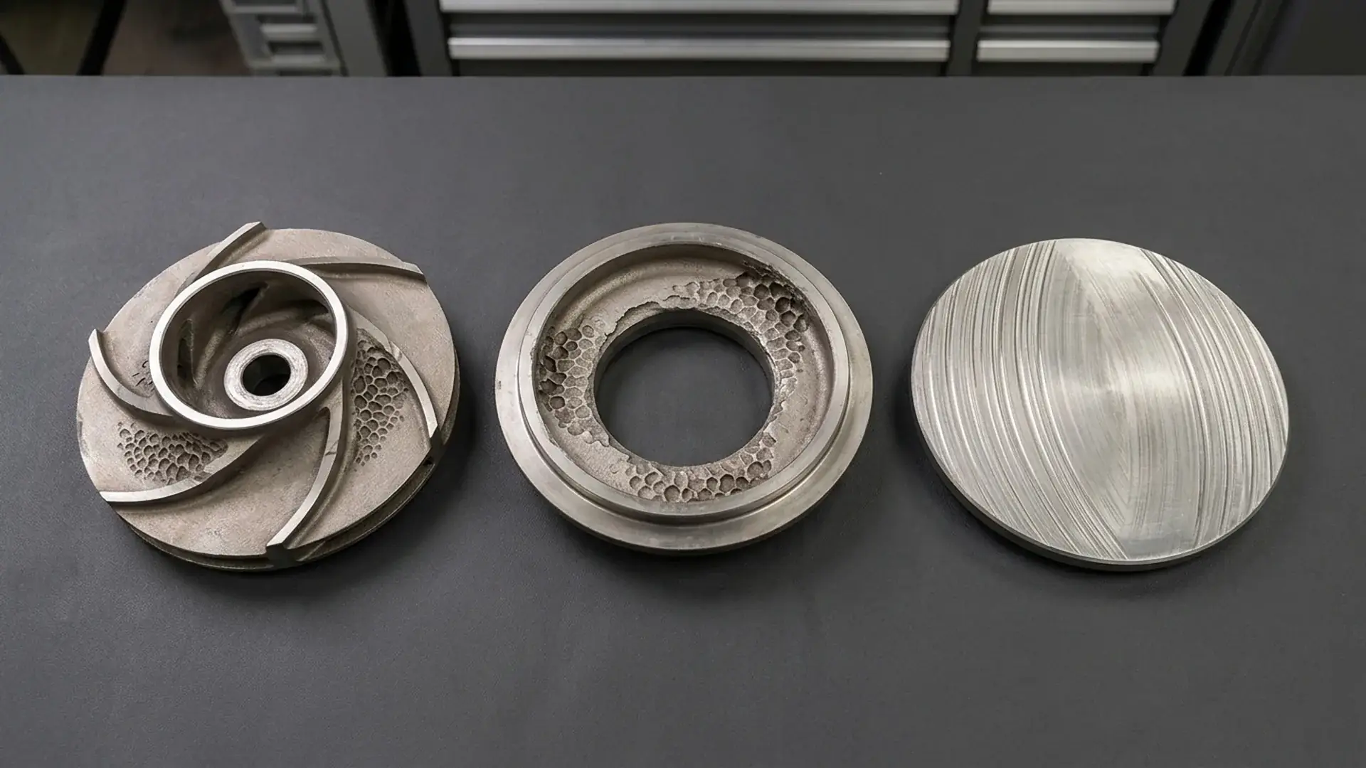
| Feature | Cavitation Damage | Abrasive Wear |
|---|---|---|
| Location | Impeller eye, vane inlet, suction liner | High‑velocity zones: vane tips, cutwater, volute |
| Surface texture | Irregular pits, honeycomb appearance | Smoother, directional scoring |
| Rate of progression | Rapid, accelerates after initial pits form | Gradual, proportional to operating hours |
| Effect on performance | Quick flow/head drop once pitting grows | Slow, steady decline |
| Associated noise | Crackling, rattling | Usually quiet, except solids impact noise |
Troubleshooting Low NPSHa in Existing Slurry Systems
When a slurry pump starts showing cavitation symptoms after years of normal operation, don't blame the pump first. The system changed — your job is to find what changed.
- Check actual liquid level. Sump levels drop over time due to siltation or process changes; a static head that was positive can drift to near zero or negative.
- Inspect suction strainer and pipe internally. Solids build‑up, scale, or a partially closed valve can create a high‑loss point that your original NPSHa calculation never considered.
- Measure actual slurry SG and solids concentration. A change in upstream process conditions (finer grinding, higher recycle loads) can raise density and friction loss silently.
- Review pump operating point. Is the pump running far to the right or left of BEP? Off‑peak flow increases suction recirculation and can drop NPSHa below the published curve.
- Check impeller clearance and wear condition. Excessive clearances after wear shift the hydraulic profile and can actually lower the pump's NPSHr slightly, but more importantly they mask the real flow rate, making it hard to interpret suction conditions.
Operational Fixes Before Replacing the Pump
- Throttle the discharge valve slightly to bring the operating point back toward BEP. This reduces suction recirculation and can buy you enough NPSH margin to stay out of cavitation until the next planned shutdown. Don't run there permanently — efficiency drops and radial loads rise.
- Reduce pump speed (if VFD‑driven). Affinity laws show NPSHr decreases with the square of speed ratio. A 10% speed reduction lowers NPSHr by about 19%, which can be the quickest emergency fix.
- Increase sump level if possible. Even 0.5 m of extra static head can swing the balance.
- Air injection check. Ensure there are no air leaks in the suction line, packing, or seal flush system; even small air entrainment amplifies cavitation.
When System Redesign Is Necessary
If you've throttled, slowed down, and cleaned the strainer and still hear that crackling, the system likely needs a piping or pump configuration change. In my experience, the three most common root causes that force redesign are: undersized suction pipe diameter (velocity too high), excessive suction lift (pump must be relocated lower), or a pump whose NPSHr is simply too high for the available site conditions. At that point, ask your supplier for an alternative pump model with a lower NPSHr or consider a vertical cantilever sump design that immerses the impeller directly in liquid — eliminating suction piping entirely.
RFQ and Supplier Verification Checklist for Slurry Pump NPSH
Don't let a supplier sell you a pump based only on a data sheet that assumes clean water. When preparing an RFQ or evaluating a quotation, push for specific slurry‑aware documentation.
| RFQ Field | What to Request / Confirm |
|---|---|
| Slurry specific gravity (min / max) | Provide your measured range; ask supplier to state NPSHa margin at max SG |
| Solids concentration (% by weight & volume) | Request suction loss correction method for your concentration |
| Particle size distribution | Ensure the pump suction nozzle and impeller eye clearance accept the max particle without clogging |
| Suction piping layout | Submit iso-drawing; ask supplier to verify NPSHa and recommend suction pipe size |
| Pump NPSHr curve | Demand the full curve, not a single point. Clarify the test standard (e.g., ISO 9906 Grade 1 or Grade 2), but recognize that NPSHr curves are almost always based on clean‑water testing unless the manufacturer explicitly documents a slurry‑specific test. |
| Recommended NPSH margin for slurry | Must be a written engineering recommendation, not a verbal promise |
| Operating range relative to BEP | Confirm allowable flow range and its effect on NPSHr |
| Material suitability | Request material traceability for high‑chrome parts; ask for erosion‑corrosion guidelines under cavitation |
| Site altitude and temperature | Supplier must factor these into NPSHa verification |
| Witnessed testing option | If the pump is critical, negotiate a witnessed hydraulic test at the factory (likely water‑based, but validates hydraulic performance) |
If you're evaluating a vertical submersible slurry pump for sump applications, look at our durable high-pressure vertical submersible slurry pump to see how suction conditions are handled by submergence.
FAQ — Slurry Pump NPSH
Below are the questions I get asked most often by project engineers and procurement teams dealing with slurry cavitation.
What NPSH margin is recommended for slurry pumps?
A minimum of 2 m above the published NPSHr is the starting point. For high‑density or variable‑concentration slurries, increase that to 3 m or more. Always confirm with the pump manufacturer — and get their margin recommendation in writing, tied to your actual slurry data.
Can cavitation occur even if NPSHa is higher than NPSHr?
Yes, especially in slurry systems. The published NPSHr is defined by a 3% head drop under clean‑water testing. In slurry, cavitation inception often starts well before you reach that head drop because of local flow disturbances and the density effect on flow fields. The standard 3% criterion misses early‑stage cavitation that still causes abrasive wear. That's why a larger margin is essential.
Does reducing pump speed lower NPSHr?
Absolutely. Per the affinity laws, NPSHr changes approximately with the square of the speed ratio. Dropping speed by 20% reduces NPSHr by about 36%. A variable‑frequency drive (VFD) gives you a powerful tool to suppress cavitation during transient slurry density increases or while waiting for piping upgrades.
Why do slurry pumps fail faster under cavitation?
Because cavitation bubble collapse hurls solid particles at metal surfaces at impact speeds that far exceed normal flow‑induced erosion. The combined fatigue‑and‑impingement mechanism can remove material 3–5 times faster than pure cavitation pitting in clean‑water pumps. The same pump in clean‑water service might run for years with mild cavitation; in slurry, it can destroy an impeller in months.
Should slurry systems use flooded suction whenever possible?
Yes. Flooded suction (positive static head) is the single most reliable way to boost NPSHa and stabilize the flow into the impeller. In hard‑rock mining and dredging, flooded suction arrangements are standard practice for high‑wear slurry duties because they eliminate suction lift and dramatically reduce air entrainment risks. If you cannot achieve flooded suction because of site layout, consider a vertical cantilever pump that submerges the hydraulic end directly.
Conclusion
Slurry pump cavitation isn't something you manage with a slightly bigger impeller or a higher‑alloy material — it demands a system‑level approach. Start with a brutally honest NPSHa calculation that accounts for slurry density, solids concentration, altitude, and worst‑case suction conditions. If your margin isn't at least 2 m over the published NPSHr, fix the suction piping first, not the pump.
The three highest‑payoff actions you can take right now: oversize the suction line, eliminate suction lift with a flooded arrangement, and demand NPSH test data and a written slurry margin recommendation from your pump supplier. Cavitation in abrasive service destroys profits — but it is predictable, measurable, and preventable if you treat slurry as a different beast than the water most textbooks describe.
Get A Quote

Get A Quote
0 Comments