
Split Case Pump Troubleshooting: Vibration, Seal & Bearing Guide
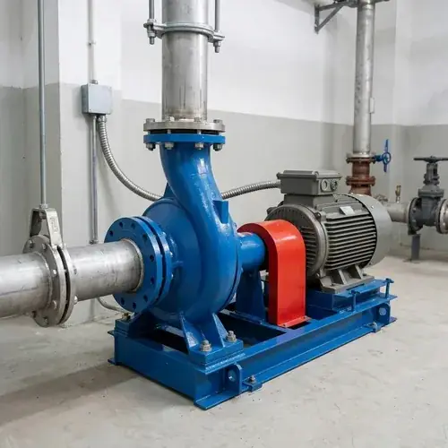
Most split case pump failures you see in the field are not isolated component failures. The bearing seizure, the seal leak, the impeller pitting — they are usually secondary symptoms triggered by something upstream. You have a misalignment problem that nobody corrected after the last overhaul. You have a suction-side restriction that dropped your NPSHa margin months ago. You have a pump that has been running at a fraction of its BEP — maybe 30% or worse — for years because the system demand changed and nobody resized the impeller.
This guide gives you a symptom-based split case pump troubleshooting path. Not a list of textbook definitions. It is written from the perspective of someone who has spent decades walking into pump houses, listening to the sound, touching the bearing housing, and working out where to look first — before the maintenance team orders another set of bearings. If you are responsible for HVAC chilled water, municipal distribution, cooling water circulation, or fire water systems where a split case pump runs 24 hours a day, the goal here is to help you confirm the root cause, decide whether the problem is mechanical, hydraulic, or installation-related, and avoid replacing the same part twice.
By the time you finish reading, you should know what to inspect first for vibration, when a seal leak points to a suction problem and not the seal itself, which bearing failure patterns signal misalignment versus cavitation, and how to decide between a repair, a full rotor rebuild, or a replacement pump procurement. And you will have a structured inspection list ready if you need to prepare an RFQ for replacement parts or a new double-suction pump.
What Makes Split Case Pumps Different in Maintenance and Failure Diagnosis
A split case pump matters in troubleshooting because its architecture changes both what can fail and how you access the problem.
The casing splits axially along the shaft centerline. You can lift the top half without disconnecting the main suction and discharge piping. That is a significant advantage when you need to inspect the rotating assembly — impeller, shaft, wear rings, and shaft sleeves — during a shutdown. In municipal and HVAC plants, this means the maintenance window can be measured in hours instead of days. But it also means that if the casing split gasket leaks, the root cause is often not the gasket material. It is the baseplate distortion or pipe strain trying to twist the casing halves relative to each other.
The impeller is a double-suction design. Water enters from both sides of the impeller eye, which balances axial thrust hydraulically. Real-world benefit: the thrust bearing load is inherently lower than a single-suction pump of equivalent capacity. But do not confuse lower axial load with zero vibration risk. If one suction side is partially blocked or the flow distribution to the two impeller inlets is uneven, the hydraulic balance breaks. You will see vibration and uneven wear ring clearance.
Practical implications for troubleshooting:
- Vibration diagnostics start differently. Because axial thrust is largely self-canceling under normal conditions, a sudden increase in axial vibration often points to a hydraulic imbalance (suction problem, cavitation, or off-BEP operation) rather than a structural bearing issue. Radial vibration spikes, by contrast, typically point to mechanical problems — coupling misalignment, rotor imbalance, or soft foot.
- Seal leakage patterns tell you more than you might think. Both shaft seal locations (inboard and outboard) see nearly the same suction pressure in a well-designed double-suction pump. If one seal fails repeatedly while the other runs fine, suspect a localized problem on that side: shaft sleeve scoring, uneven thermal growth, or a specific alignment issue.
- Maintenance access can hide problems. Because the pump stays in the pipe rack during inspection, field crews sometimes skip alignment verification after reassembly. That shortcut is a leading cause of repeat bearing failures within the first few hundred operating hours post-overhaul.
Split case pumps typically live in high-flow, medium-head municipal water, district cooling, industrial cooling water, and fire protection applications. They are often the largest pump in the building — it is rarely practical to keep a complete spare rotor set onsite. When one goes down, the cost is not the bearing price; it is the building that loses chilled water or the treatment plant that drops a distribution zone. That is the commercial reality behind why a correct root-cause diagnosis matters far more than the cost of the repair part.
Image Planning Note — Split Case Pump Cutaway Diagram
Buyer Question Answered: How does a split case pump differ internally, and why does maintenance access not require removing the piping?
Must-Show Components: Horizontal split casing halves (axially split along shaft centerline), double-suction impeller with flow entering from both sides, shaft, bearing housings (both ends), mechanical seal locations, and wear rings.
Realistic Layout and Visuals: A clean, engineering-style cross-section cutaway; arrows indicating suction flow from both sides to the impeller eye and discharge flow; bolt locations showing how the casing opens.
Forbidden Image Mistakes: Decorative CGI or unrealistic flow paths; missing shaft support; making the impeller look like a single-suction design.
Suggested File Name: split-case-pump-cutaway.png
Quick Diagnostic Chart for Common Split Case Pump Symptoms
The table below is a fast-triage tool. Use it when you first walk up to the pump and need to prioritize inspections. Do not take it as the final answer — it narrows the diagnosis path, but you still need to verify with measurements.
| Symptom | Most Likely Causes (start here) | First Inspection Point | Urgency |
|---|---|---|---|
| High vibration (radial) | Coupling misalignment, rotor imbalance, soft foot, loose baseplate | Check coupling alignment (dial indicator or laser); verify baseplate bolt torque | Schedule shutdown within days; monitor trend |
| High vibration (axial) | Cavitation, operation far from BEP, uneven suction flow to double-suction inlets | Measure suction pressure, compare to NPSHr + margin; check flow vs BEP | High — investigate immediately |
| Bearing overheating (housing temperature elevated) | Grease degradation, over-greasing, misalignment, excessive radial load | Measure housing temperature at load zone; compare to manufacturer’s alarm limit (commonly around 80°C but verify); check recent grease quantity and type | Monitor; if rising fast, prepare for shutdown |
| Seal leakage (continuous drip) | Worn seal faces, shaft sleeve scoring, misalignment, dry running | Inspect seal flush line for blockage; check shaft sleeve surface under seal | Schedule repair at next available window |
| Seal leakage (at startup only) | Thermal shock, suction pressure instability during priming, seal faces sticking after idle period | Verify venting and priming procedure; check if system experiences pressure surges on startup | Medium — monitor pattern |
| Abnormal noise (gravel-like sound) | Cavitation | Record suction pressure gauge reading; check suction strainer/valve position | High — cavitation damages impeller quickly |
| Abnormal noise (metallic knock) | Loose coupling element, bearing spalling, foreign object | Stop pump; inspect coupling element condition | Critical — stop and inspect immediately |
| Low flow / low discharge pressure | Worn wear rings, suction blockage, partially closed discharge valve, impeller erosion | Compare discharge pressure to original test curve at same flow; measure pump differential head | Medium — efficiency loss adds energy cost daily |
| Motor overload / high amps | Operation too far right on curve (low head / high flow), worn wear rings allowing excessive recirculation, liquid SG higher than design | Measure actual flow and head; compare motor current to rated FLA at measured operating point | High — risk of motor winding damage |
Split Case Pump Vibration Troubleshooting
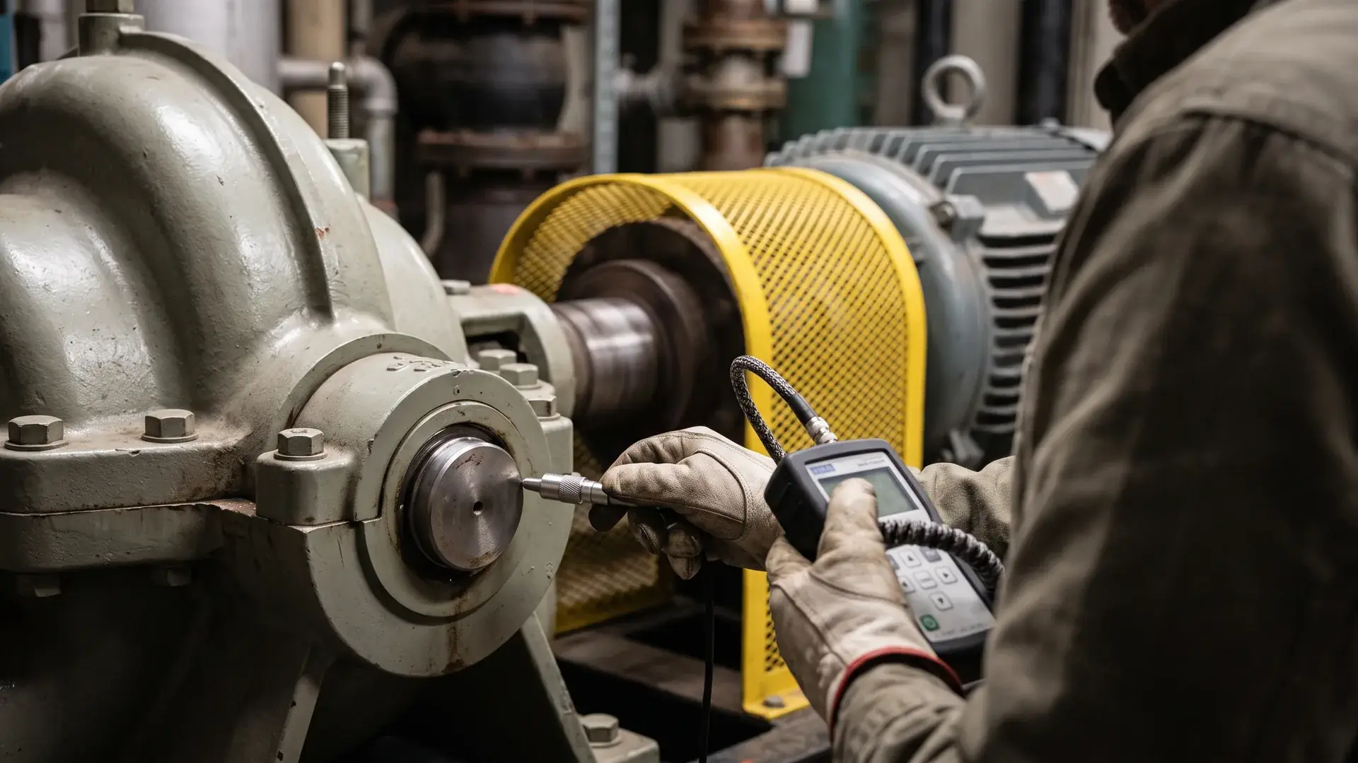
Vibration is the single most common complaint on split case pumps in continuous-duty service. The challenge is not measuring it — most plants already have vibration meters or installed accelerometers. The challenge is separating hydraulic vibration from mechanical vibration, because you fix them completely differently. Replace bearings to address a hydraulic cavitation problem, and you will be back in the pump a month later swearing at the same failed bearings.
Start with one principle: measure first, act second. Take vibration readings at the bearing housings in all three axes (horizontal, vertical, axial) and trend them against the pump's operating history. A sudden jump often signals a specific event — a valve position change, a suction strainer that loaded up, a coupling that shifted. A gradual increase over months is more likely wear-related — bearing degradation, increasing wear ring clearance, progressive shaft sleeve pitting.
Now, separate the causes.
Mechanical Causes of Split Case Pump Vibration
Mechanical vibration usually shows as dominant radial (horizontal/vertical) vibration at running speed (1× RPM). It does not disappear when you change flow rate through the pump.
Coupling misalignment is the most common culprit, and it is also the most commonly introduced during maintenance. After any rotor reassembly, thermal growth changes the alignment target. A pump aligned cold at 20°C can shift by a measurable amount — 0.05 mm to 0.1 mm or more, depending on the pump size and temperature differential — at its operating temperature of 60°C or 80°C. If your alignment procedure does not account for thermal growth offsets (provided by the pump manufacturer), you are aligning to the wrong target. For a deeper dive into alignment diagnosis, see our guide on pump shaft misalignment causes and fixes.
Soft foot is the next thing to check. A casing foot that does not sit flat on the baseplate — even with the bolts tightened — introduces a twist into the casing when you torque the bolts. On a split case pump, that twist can open the casing split joint and cause a gasket weep, on top of loading the bearings unevenly. Check with a feeler gauge under each foot before torquing.
Rotor imbalance can be residual (from the factory or a previous impeller repair) or progressive (cavitation eroding impeller material unevenly, or corrosion products building up inside the impeller passages). If balancing was done with the impeller only (not the full rotor assembly), field balance may still be off. After any impeller rework, request a full-rotor balance report, not just the impeller balance certificate.
Pipe strain is sneaky. Pipe flanges bolted to the pump suction and discharge nozzles should not require force to align. If you have to use a come-along or long pry bar to get bolt holes to match, the pump casing is carrying piping load. Disconnect the flanges and check the gap and parallelism by feel. A noticeable gap difference, even a fraction of a millimeter, across the flange diameter is a red flag.
Loose baseplate or foundation bolts can produce vibration that mimics bearing failure. Before opening the bearing housing, check every anchor bolt with a torque wrench. A hollow-sounding grout area under the baseplate (found by tapping with a hammer) means the foundation is not supporting the pump evenly.
Hydraulic Causes Including Cavitation and Off-BEP Operation
Hydraulic vibration often contains broadband energy and changes character when you change the pump's operating point. It typically increases when you move farther from the Best Efficiency Point (BEP).
Cavitation produces a characteristic sound — like gravel or marbles passing through the pump — and often shows elevated vibration in the higher-frequency range. It also has a specific failure pattern: impeller material is removed (pitting) on the suction side of the vanes, and over time the impeller loses material, balance degrades, and the bearing housings start shaking. Cavitation is fundamentally an NPSHa-versus-NPSHr problem, but the practical causes on split case pumps usually involve suction piping: a partially closed suction valve, a clogged strainer or intake screen, a suction pipe diameter smaller than the pump inlet, or an elbow too close to the pump suction. We cover the full diagnosis logic in our pump cavitation troubleshooting guide.
Operation far from BEP generates hydraulic instability — flow recirculation at the impeller inlet (when running at low flow) or discharge recirculation (at high flow). The vibration created by recirculation can be severe and can damage both bearings and seals. A pump that was sized for a future peak load that never came is often running at 40–50% of BEP continuously, vibrating more than it should, and nobody connects the two because "it still delivers the required flow."
Uneven flow into the double-suction inlets is specific to split case pumps. If the suction piping approach is not symmetrical — an elbow directly on one side of the suction inlet, for example — one impeller eye gets more flow than the other. Axial thrust reappears, and you see elevated axial vibration. The fix is usually a suction piping modification: a straight run of at least 5–7 pipe diameters before the suction connection, or a suction diffuser.
When Vibration Requires Shutdown
Every pump has a vibration severity envelope. Standards such as ISO 10816-3 and ANSI/HI 9.6.4 define acceptable vibration limits for different machine categories; for split case pumps, these standards group based on pump size, speed, and mounting. The actual limit therefore depends on the specific machine class and the manufacturer's verified data — do not treat the following as universal thresholds. A general practical example for medium-size split case pumps in the 30–200 kW range on rigid foundations, often seen in guidance documents:
- Up to about 4.5 mm/s RMS (rigid-mounted) is typically acceptable for continuous operation.
- Between 4.5 and 7.1 mm/s RMS — investigate, trend, and schedule corrective action.
- Above 7.1 mm/s RMS — corrective action should be planned promptly.
- A sudden change of more than roughly 1.5–2 mm/s RMS over a short period (hours to days) warrants immediate inspection, even if the absolute value is still "acceptable."
But those are reference ranges, not universal limits. Always check the pump manufacturer's recommended vibration limits for the specific model and confirm which edition of the applicable standard (ISO 10816-3, ANSI/HI 9.6.4, or equivalent) applies to the installed machine.
Image Planning Note — Vibration Cause Comparison
Buyer Question Answered: What separates mechanical vibration from hydraulic vibration?
Must-Show Components: A side-by-side visual comparison — one side illustrating mechanical causes (misalignment, soft foot, pipe strain) with exaggerated shaft offset and force arrows; the other side illustrating hydraulic causes (cavitation, off-BEP recirculation, uneven suction flow) with pressure and flow disturbance indicators.
Realistic Layout and Visuals: Two clear panels; on the mechanical side show coupling offset, foot shim gap, and piping pushing against the flange; on the hydraulic side show vapor bubble formation at the impeller eye and asymmetric suction flow.
Forbidden Image Mistakes: Generic motor stock photos; cartoon vibration waves with no connection to pump components; unrealistic coupling geometry.
Suggested File Name: split-case-vibration-causes.png
Bearing Failure and Overheating Diagnosis
Bearings rarely fail in isolation. A bearing that runs hot, gets noisy, or seizes is usually the victim of something else: misalignment loads, vibration from cavitation, lubrication contamination, or shaft currents. The safest assumption is that a bearing failure is a consequence, not the root cause, unless you have clear evidence otherwise.
Early Warning Signs Before Bearing Seizure
You want to catch bearing degradation before it becomes a seizure that scores the shaft or cracks the housing. The sequence typically goes:
- Temperature rise. A rolling-element bearing in a split case pump runs warmer than ambient under normal conditions — typically 15°C to 30°C above ambient, though this varies with load and bearing type. If you see a housing temperature rising above the normal range (e.g., exceeding 75–80°C and still climbing under stable operating conditions), something is changing. Confirm the acceptable alarm limit for your specific pump model. Check with an infrared thermometer or installed RTD.
- Noise change. A failing bearing often produces a high-frequency ringing or whining sound early on. As damage progresses, you may hear a rhythmic clicking or rumbling. Listening with a contact probe or even a screwdriver handle against the housing can distinguish bearing noise from hydraulic noise.
- Vibration trend shift. Bearing degradation shows as increasing vibration energy at non-synchronous frequencies — bearing fault frequencies related to inner race, outer race, ball, and cage. A vibration spectrum analyzer can pick this up well before the bearing is near seizure.
- Grease appearance. During a scheduled relubrication, if old grease purged from the bearing looks metallic, contains dark particles, or smells burnt, do not just add fresh grease and walk away. The bearing is already degrading.
Common Root Causes Behind Repeat Bearing Failure
If you replace the same bearing position twice in a year, the problem is not the bearing quality. Suspect the following:
- Coupling misalignment after reassembly. Every new bearing install should include a fresh alignment check after the pump reaches operating temperature. Cold alignment is a starting point; hot alignment is the truth. If your facility cannot do a hot alignment check on a large split case pump, at least apply the manufacturer's thermal growth offset values.
- Over-greasing. Too much grease churns, overheats, and degrades the lubricant — exactly the condition that accelerates bearing failure. Grease fill should be around 30–50% of the bearing cavity free volume for many bearing types (confirm from the bearing manufacturer’s recommendation). Purge the old grease, inject fresh slowly while the rotor turns, and stop when you feel a slight resistance increase or see clean grease emerging. Wipe the excess.
- Cavitation-induced vibration transmitted to bearings. Even if the bearing is mechanically perfect, high-frequency vibration from impeller cavitation hammers the rolling elements against the races. Over time, false brinelling or surface fatigue spalling appears. The bearing failure looks like a classic fatigue problem, but the root cause is hydraulic. For the full bearing diagnostic path, see our dedicated article on pump bearing failure diagnosis.
- Contamination. Water ingress through worn bearing isolators or lip seals turns grease into an emulsion. Even a small amount of moisture dramatically reduces bearing life. If you find rusty-colored grease or free water in the housing, fix the sealing before replacing the bearing.
- Shaft currents (VFD-driven pumps). If the pump motor is on a variable-frequency drive and the motor shaft is not properly grounded, induced shaft currents can arc through the bearing balls and races, producing a characteristic "fluted" or washboard pattern on the race surface. This is a VFD/grounding problem, not a bearing quality issue.
Repair vs Full Rotor Inspection Decision
After the first unexpected bearing failure: replace the bearing, verify alignment, check lubrication, and return to service. That is a reasonable repair decision if there is no other evidence of damage.
After the second failure of the same bearing position within the same service year: the bearing is a symptom. Open the pump at the next opportunity and inspect at least the shaft journal under that bearing (for scoring, fretting, or diameter reduction beyond tolerance), the bearing housing bore (for out-of-round or wear), the coupling alignment at temperature, and the impeller condition (for cavitation or imbalance evidence). A full rotor inspection — shaft runout, wear ring clearances, balance condition — is justified at this point.
Image Planning Note — Bearing Failure Development Map
Buyer Question Answered: How do bearing failures develop from root causes?
Must-Show Components: Bearing housing cross-section showing rolling elements, races, lubrication path; overlay arrows indicating vibration transmission from misalignment, cavitation, and over-greasing; heat zones around the bearing.
Realistic Layout and Visuals: A labelled cutaway of a pump bearing housing with connecting lines to root causes — cavitation vibration path through shaft, misalignment radial force, grease churning and thermal degradation, water contamination path.
Forbidden Image Mistakes: Impossible bearing assembly (missing cage or seals), generic angular-contact bearing that does not reflect pump bearing configurations.
Suggested File Name: pump-bearing-failure-map.png
Seal Leakage Causes in Double-Suction Pumps
Mechanical seal leakage on a split case pump can be either a seal problem or a system problem telling you something through the seal. Knowing the difference saves you from replacing the same seal cartridge three times.
On a double-suction pump, the seal chambers are typically at suction pressure (plus a small increase from the stuffing box or seal chamber geometry). The seals are not seeing a high-pressure differential like a single-stage end-suction pump operating near shutoff. That means when a seal leaks on a split case pump, high pressure alone is rarely the cause. Look elsewhere.
Leakage During Startup vs Continuous Leakage
Seal leaks only at startup, then stops. This pattern frequently points to seal face sticking after a long idle period. When the pump sits idle for weeks or months, the seal faces can adhere lightly, especially if the pumped liquid leaves deposits. On startup, the faces break free with a small puff of leakage, then seat under hydraulic pressure and seal normally. If the leakage stops within seconds to a minute and does not recur, it is usually a minor operational issue. Check the seal flush and venting arrangement to confirm the seal chamber fills properly before startup — a dry start can cause more serious damage.
Continuous drip or stream. This points to damaged seal faces, worn secondary seals, or shaft sleeve scoring under the seal. But do not stop at the seal components. Ask:
- Is the seal flush line clogged? A blocked flush or cooling line means the seal runs dry or overheated, even if suction pressure is present at the pump inlet.
- Is there detectable radial shaft movement at the seal chamber? If coupling misalignment or bearing wear allows the shaft to orbit more than the seal's radial compliance limit (often around 0.1–0.2 mm for many cartridge seals, but verify with the seal manufacturer), the seal faces open intermittently and leak.
- Has the pumped liquid changed? A new treatment chemical, higher solids loading, or different temperature can change seal compatibility. The seal that ran for three years on treated water may fail in weeks on a slightly more aggressive water chemistry.
How Cavitation and Misalignment Damage Seals
Cavitation near the impeller inlet creates pressure pulses that travel through the liquid to the seal chamber. Those pulses flex the seal faces microscopically and can cause face chipping or fatigue cracks over time. The damage pattern on the seal faces — often radial cracks or small edge spalls — is a clue. If the failed seal shows that pattern and the impeller also shows cavitation pitting, fixing the seal without fixing the suction condition is a waste of time.
Misalignment damage to seals is more mechanical. If the shaft axis is not aligned with the seal chamber bore axis (due to pipe strain, casing distortion, or bearing housing misalignment), the seal rotary face does not run true against the stationary face. One side of the seal face wears more heavily than the other — you can sometimes see uneven wear band width on the carbon face. The comprehensive diagnosis path, including seal face analysis and corrective steps, is covered in our pump seal troubleshooting guide.
Cavitation in Split Case Pumps
Cavitation is the one failure mode that you can often diagnose without disassembling anything — if you know what to listen for and what pressure gauges to trust.
In a split case pump, cavitation starts in the low-pressure zone at the impeller eye inlet, exactly where the double-suction inlets direct liquid onto the vanes. The sound is unmistakable once you have heard it: a crackling, gravel-like noise, distinct from the smoother hum of the pump under normal flow. If you hear that sound and your suction pressure gauge needle is vibrating or reading lower than expected, you are likely dealing with insufficient NPSH margin.
The core equation never changes: NPSHa (available) must exceed NPSHr (required by the pump at the operating flow) by a safe margin — often 0.5 m to 1.0 m or more for medium-size split case pumps in water service, and even more if the liquid contains entrained air or operates near its vapor pressure. But the field problem is rarely about doing the calculation. It is about what changed: a new strainer installed upstream, a suction valve that drifted partially closed over months, a reservoir water level that dropped in dry season, or a system flow demand increase that pushed the pump to the right on its curve where NPSHr is higher.
Common Suction-Side Mistakes
- Suction pipe diameter smaller than the pump suction flange, creating a permanent high-velocity inlet with extra friction loss.
- An elbow directly on the pump suction inlet (no straight run), which introduces uneven flow distribution and a local low-pressure zone at the elbow inside radius.
- A foot valve or check valve on the suction side with debris holding it partially open, acting as a throttle.
- Suction lift application on a pump originally designed for a flooded suction — the NPSHa may have been acceptable at commissioning but dropped as the foot valve or suction pipe aged.
- A "temporary" suction strainer installed for commissioning and never removed, now partially clogged.
Cavitation Damage Patterns on Double-Suction Impellers

When you open a split case pump and pull the top casing half, look at the impeller inlet areas. Cavitation pitting appears as rough, sponge-like metal removal on the visible (low-pressure) side of the vanes near the inlet edges. On a double-suction impeller, if the damage is worse on one side than the other, that points to uneven flow distribution — one suction inlet is starving relative to the other. If both sides show similar pitting, the NPSH deficiency is likely global — total suction pressure is too low for the operating point.
The comparison table below helps connect damage location to root cause:
| Cavitation Damage Pattern | Likely Root Cause | Verification |
|---|---|---|
| Pitting on both impeller eye inlets, similar severity | Global NPSHa deficiency | Measure suction pressure at pump inlet; compare to NPSHr + margin at operating flow |
| Pitting significantly worse on one impeller eye inlet | Uneven suction flow distribution (elbow too close, partially blocked one-side strainer) | Inspect suction piping layout; check for asymmetric fittings |
| Pitting concentrated at vane tips near outer diameter | Suction recirculation at low flow (pump operating far left of BEP) | Measure flow; confirm pump is not running below minimum continuous stable flow |
| Erosion plus pitting (material loss smoother) | Combined cavitation and abrasive wear from solids in liquid | Check liquid solids content; inspect wear ring clearance increase |
Image Planning Note — Cavitation Damage on Double-Suction Impeller
Buyer Question Answered: What does cavitation damage look like, and how does it relate to suction conditions?
Must-Show Components: Close-up of a double-suction impeller inlet area with rough pitting on the low-pressure side of the vanes; highlight the difference between symmetrical pitting (both eyes damaged) and asymmetrical pitting (one eye significantly worse).
Realistic Layout and Visuals: Photo-realistic or carefully drawn damaged impeller face with labels pointing to pitted areas; include a small inset showing the vapor bubble collapse mechanism near the vane surface; suction pressure loss symbols.
Forbidden Image Mistakes: Exaggerated explosion visuals; making the impeller look like a single-suction design; showing pitting on the wrong side of the vane.
Suggested File Name: split-case-cavitation-damage.png
Low Flow, Noise, and Motor Overload Checks
These three symptoms often show up together or in sequence, and they typically trace back to either a hydraulic system change or internal pump wear. Distinguishing them quickly avoids ordering the wrong repair parts.
Low flow that develops gradually over months is often wear-related: increasing wear ring clearance allows internal recirculation, or impeller vane erosion reduces hydraulic efficiency. The pump still runs, the motor is not tripping, but discharge pressure at a given valve position slowly drops. Track this by trending discharge pressure at a standard flow condition. If differential head across the pump drops significantly — say, 8–10% or more — from the baseline curve, the wear rings and impeller clearance need inspection.
Low flow that appears suddenly points to a system change: a valve position shifted, a suction strainer clogged, or a pipe blockage. Check valve positions first — it costs nothing and is the most common cause. A sudden drop in pressure accompanied by increased noise often means a foreign object in the impeller or a suction-side air leak.
Abnormal noise without obvious vibration or performance loss can be a trapped air pocket in the casing or suction line. Split case pumps require proper venting during startup; the top of the casing should have a vent plug or valve to bleed air before the pump runs. If venting is skipped, an air pocket remains at the casing high point and produces a gurgling or knocking sound that comes and goes.
Motor overload / high amps needs immediate attention to avoid winding damage. On a split case pump, three things commonly cause overload:
- Pump running too far right on the curve — flow is high because discharge head is low (open bypass, oversized pipe, multiple pumps in parallel with one throttled back less than the rest). The power curve of a centrifugal pump rises with flow; if it runs out beyond the design range, motor amps climb. Confirm by checking actual flow versus the design duty point.
- Liquid density higher than design — the pump was sized for water at 1.0 SG, but you are now pumping a fluid with a density of 1.1 or 1.2. Motor power is directly proportional to density. This is common in process applications where a fluid composition changed.
- Worn wear rings allowing high internal recirculation — the motor must deliver additional power to recirculate flow from discharge back to suction through the worn clearance. The pump "thinks" it is moving more mass flow than the discharge pipe actually sees. For a more detailed look at overload conditions, refer to our article on why a pump overloads at full flow.
Repair, Rebuild, or Replace? Practical Decision Criteria
When a split case pump has been in service for years and starts showing multiple symptoms — vibration, seal leaks, and bearing temperature rise together — you face a real procurement decision: invest in a rotor rebuild, or replace the entire pump set.
There is no universal formula that makes this decision for you. But the following criteria shift the tipping point one direction or the other, based on what I have seen in municipal, HVAC, and industrial plants over decades.
Factors that favor repair/rebuild:
- Casing pressure boundary is intact — no significant corrosion, pitting, or wall thinning that affects pressure integrity. A minor split-joint gasket leak that resolves with proper bolt torque and flatness check is repairable.
- Shaft runout is within the manufacturer's tolerance (confirm from the pump manual; a typical range for medium-size split case pumps is 0.025–0.05 mm TIR, but verify). No cracking or fretting at the impeller keyway.
- Impeller wear is limited to wear rings and clearances, with vane geometry still largely intact. Worn wear rings can be replaced; impeller diameter can be slightly trimmed to restore efficiency if material remains.
- Spare parts availability is good — bearings, mechanical seals, wear rings, shaft sleeves, and casing gaskets are standard commercial items, not obsolete proprietary parts.
- The pump baseplate and foundation are still solid — grout is intact, anchor bolts torque properly, no structural cracking.
Factors that push toward replacement:
- Casing or casing cover shows significant internal erosion or pitting that reduces wall thickness below minimum required. This is hard to measure accurately in the field; if in doubt, request an ultrasonic thickness survey.
- Repeated rotor-related failures (bearings, seals) in the same year with confirmed correct alignment, lubrication, and operating conditions — this often signals accumulated shaft fatigue or a housing bore that is no longer maintaining bearing fit tolerance.
- Efficiency has dropped by more than roughly 10–15% from original and the energy cost delta over the next 5–7 years of operation could exceed the replacement pump capital cost. This calculation matters a lot on large split case pumps running 8,000+ hours per year. Even a 5-point efficiency loss on a 200 kW pump can add up to tens of thousands of dollars in wasted electricity over its remaining service life.
- The pump duty has changed and the existing unit no longer operates near its BEP — a new pump can be sized specifically for the current (not original) system curve, recovering efficiency and reducing vibration.
| Decision Factor | Favors Repair | Favors Replace |
|---|---|---|
| Casing integrity | Intact, no significant corrosion | Wall thinning, deep pitting, or cracking |
| Shaft condition | Runout within spec, no fretting | Runout exceeds spec, keyway or diameter damage |
| Impeller condition | Wear limited to replaceable wear rings | Vane erosion beyond rebalancing, excessive tip clearance |
| Spare parts | Standard bearings, seals, wear rings available | Obsolete parts, long lead times, custom seal chambers |
| Efficiency | Within roughly 5–8% of original | More than roughly 10–15% efficiency loss on a continuous-duty pump |
| Operating hours history | Moderate (intermittent or seasonal) | Very high (e.g., 8,000+ hrs/year for >15 years) |
| Downtime cost | A rebuild can be completed in a planned window | Repeated unplanned outages cost more than a new pump |
Inspection Checklist Before Ordering Repair Parts or a Replacement Pump
When you decide to proceed with a repair or replacement, the quality of the information you provide to the supplier, service center, or OEM directly determines whether you get the right parts on the first try — or a surprise during reassembly.
Collect the following before you call or send an RFQ:
- Pump nameplate data — model, serial number, rated flow, rated head, speed (RPM), year of manufacture if available.
- Current operating point — measured or estimated flow and discharge pressure under normal operation, plus any known seasonal range.
- Vibration history — most recent readings at each bearing housing in horizontal, vertical, and axial directions, plus trend data if you have it (is vibration stable, rising slowly, or jumping?).
- Bearing temperature readings — housing temperatures at both drive-end and non-drive-end bearings under steady operation, plus ambient temperature for reference.
- Seal leakage description — continuous or intermittent? Only at startup? Has the seal been replaced before, and if so, when?
- Motor data — frame size, power (kW or HP), voltage, full-load amps, whether VFD-driven, and if VFD, the typical operating speed range.
- Liquid conditions — fluid type, specific gravity, temperature range, solids content (if any), presence of chemicals or treatment additives.
- Suction arrangement — flooded suction or suction lift? Suction pipe diameter and approximate straight-run length before the pump inlet. Any strainer, foot valve, or check valve on suction side?
- Photos or video (if available) — of the pump installation including suction piping layout, coupling area, and any visible leakage or damage.
- Original pump performance curve — if you still have it. If not, the pump model number allows the supplier to retrieve the factory curve.
Providing this level of detail up front, instead of just asking "price and delivery for a split case pump bearing and seal," changes the conversation. The supplier can identify whether the parts you requested are the ones you actually need, and whether there is a pattern suggesting a different root cause.
FAQ on Split Case Pump Troubleshooting
Here are the questions maintenance engineers ask most frequently when they first suspect a split case pump problem isn't a simple bearing or seal swap.
Why does a split case pump vibrate more after a bearing replacement?
Assuming the new bearing is correctly installed and the right type, increased vibration after bearing replacement often points to an alignment issue introduced during reassembly. The most common mistakes: reinstalling the bearing housing without checking the coupling alignment at operating temperature, ignoring soft foot under the casing feet, or using a gasket shim stack that changed the shaft centerline height. Hot alignment verification after a few hours of operation should be the standard follow-up step.
Can cavitation destroy bearings?
Yes, indirectly. Cavitation does not directly remove bearing material, but the high-frequency pressure pulses and vibration it generates travel through the shaft and into the bearing rolling elements and races. Over time, this produces surface fatigue, false brinelling, or spalling. The bearing failure looks like a classical fatigue problem, but the root cause is a hydraulic suction-side deficiency. Replacing the bearing without fixing the suction condition just restarts the clock on the next failure.
What vibration level requires immediate shutdown on a split case pump?
There is no single shut-it-down number that applies to every pump size, speed, and mounting. The more important trigger is the rate of change. A vibration reading that jumps from 3.5 mm/s RMS to 6.0 mm/s RMS in a few hours is more alarming than a pump that has run steadily at 6.5 mm/s RMS for years. If the vibration increase is combined with a change in sound (especially the onset of a metallic knock or gravel-like noise), shut down and inspect the coupling element and impeller. Always reference the pump manufacturer's own vibration severity limits and the applicable standard — ISO 10816-3 or ANSI/HI 9.6.4, depending on the machine class — for the specific unit.
Why does the mechanical seal leak only at startup?
This usually indicates seal face sticking after a period of idleness, or thermal shock when cold liquid hits a seal that was at ambient temperature. If the leakage stops within a minute or so and does not recur during the run, it is typically an operational issue, not a seal defect. Check that the seal chamber is being properly vented before startup and that the seal flush arrangement is functioning. Repeated startup-only leakage that worsens over time can indicate the seal faces are degrading and should be inspected at the next opportunity.
What causes low flow in a double-suction pump that still runs?
The common causes, in order of likelihood: a partially closed suction or discharge valve, a clogged suction strainer or intake screen, worn wear rings allowing excessive internal recirculation, impeller vane erosion reducing hydraulic performance, or air entrainment in the suction line reducing effective flow area. Check valve positions first, then suction strainer differential pressure if a gauge is installed, then trend discharge pressure against the original pump curve. If differential head is low and the impeller hasn't been inspected in years, opening the casing to measure wear ring clearance is the next logical step.
How often should coupling alignment be checked on a split case pump?
For pumps in continuous-duty service (HVAC, municipal water, process cooling), alignment should be verified at least annually. After any maintenance that disturbs the rotor, bearings, or casing — including a bearing replacement or seal replacement — alignment must be rechecked cold and, if possible, checked hot after the pump stabilizes at operating temperature. A pump on a VFD that cycles frequently between low and high speed may benefit from alignment checks every six months due to the thermal cycling effect on the baseplate and casing position.
When should a split case pump be replaced instead of repaired?
Replacement becomes the better economic decision when the casing shows significant internal erosion or wall thinning, when the shaft has been damaged beyond reconditioning (runout, keyway cracking, or undersized bearing journals), when efficiency has dropped by more than roughly 10–15% on a pump that runs 6,000+ hours per year, or when the pump duty has changed permanently and the existing unit no longer operates within an acceptable range of its BEP. If you are facing a third major rotor-related failure within two years despite confirmed correct alignment and lubrication, consider that the rotor might have accumulated fatigue damage that a rebuild cannot economically resolve — a replacement rotor or full pump replacement may be justified.
Conclusion
Here is the sequence I still follow after all these years, and it rarely leads me wrong: when a split case pump starts complaining — vibration, heat, noise, leakage — verify the operating point first. Are you anywhere near BEP? If not, every other diagnosis is suspect. Next, measure alignment. Do not assume the last person got it right; check it yourself, and if the pump runs hot, check it hot. Third, look hard at the suction side: pressure, strainers, valve position, pipe layout. Roughly half the split case pump failures I have seen in municipal and HVAC plants started as a suction-side problem that got misdiagnosed as a bearing or seal fault.
Replace parts only after you have confirmed the root cause. Bearings and seals are expensive messengers — they tell you something is wrong, but killing the messenger by swapping the part never fixes the system. If you suspect multiple interacting failures (cavitation plus misalignment plus worn wear rings), the priority order matters: fix the suction condition first, then align correctly, then address wear clearances. This approach prevents the demoralizing cycle of unplanned downtime, emergency part orders, and repeat failures that erodes both system reliability and the maintenance team's confidence.
References and Applicable Standards
- ISO 10816-3: Mechanical vibration — Evaluation of machine vibration by measurements on non-rotating parts — Part 3: Industrial machines with nominal power above 15 kW and nominal speeds between 120 r/min and 15 000 r/min when measured in situ. Provides vibration severity zones for rigid and flexible mountings; always verify the machine category and manufacturer-specific limits.
- ANSI/HI 9.6.4: Rotodynamic Pumps — Guideline for Vibration Measurements and Allowable Values. Offers practical vibration acceptance criteria for horizontal split case pumps and other rotodynamic machines; supplement with the pump OEM manual.
- Manufacturer maintenance manuals and engineering documentation: Always the primary source for alarm thresholds, alignment offsets, bearing temperature limits, seal environmental limits, and inspection intervals. No general guide can replace the model-specific data supplied with the pump.
These standards and documents should be consulted when setting vibration alarm and shutdown thresholds, interpreting trend data, and confirming whether a measured value is acceptable for a given split case pump installation. Where a standard or manual gives a specific limit, that limit takes precedence over any general range offered here.
Get A Quote

Get A Quote
0 Comments