
Horizontal Multistage Pump Buyer’s Guide: Design, Pressure, Applications
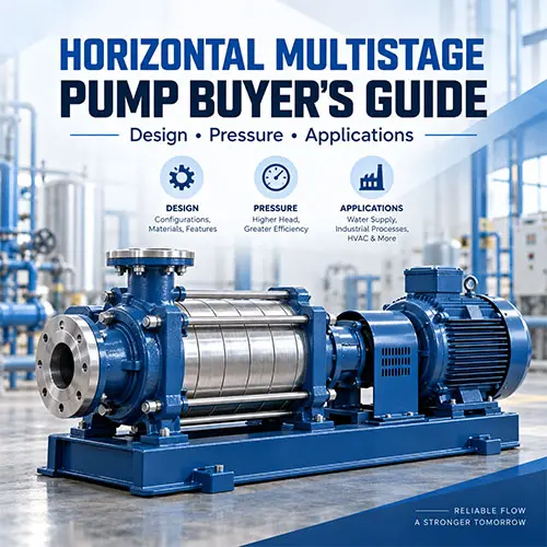
A horizontal multistage pump is a centrifugal pump with multiple impellers stacked in series on a single horizontal shaft. Each impeller (or stage) adds kinetic energy to the fluid, converting it to pressure in a diffuser or volute before passing it to the next stage. The result: discharge pressures that a single-stage pump can’t touch—often 10 to 40 bar or more—without requiring oversized, low-efficiency impellers.
If you’re selecting a pump for a boiler feed system, an RO high-pressure feed, a high‑rise pressure‑boosting station, or any clean‑liquid application that demands high head with stable flow, you’re almost certainly comparing horizontal multistage configurations. Get a few key internal design choices wrong—axial thrust balance, material compatibility, NPSH margin—and a pump that looks perfect on paper can turn into a maintenance headache within the first few years of service. The stakes are high, and the cost of a bad choice usually shows up long after the pump is on site.
This guide walks through exactly what you need to verify, and what many suppliers won’t volunteer unless you ask. We’ll cover how pressure builds stage by stage, how to read through a supplier’s thrust‑balancing claims, which design type (ring‑section or barrel) makes sense for your operation, and what documentation to demand before you issue a purchase order. By the end, you’ll have a practical framework for comparing horizontal multistage pump suppliers—not on promises, but on engineering and verifiable test data.
What Is a Horizontal Multistage Pump?
A horizontal multistage pump is distinguished by two things: the shaft runs parallel to the ground, and the pump contains at least two impellers that operate in series. The clean‑liquid impellers sit inside diffuser casings, and flow moves from the suction nozzle through each impeller/diffuser pair sequentially. Because each stage raises the fluid pressure incrementally, the total head nearly equals the sum of the individual stage heads (minus interstage losses). This makes it the go‑to configuration when a system requires discharge pressure above roughly 15–20 bar—above the practical limit for most single‑stage end‑suction pumps without sacrificing efficiency.
That horizontal shaft orientation is often decisive in industrial plants. It means the pump can be inspected and serviced at floor level without pulling the motor or disturbing the suction piping (especially on back‑pullout designs). In contrast, vertical multistage pumps—while space‑saving—tend to be harder to service and more vulnerable to problems when suction conditions fluctuate.
Buyers should think of the horizontal multistage pump as a high‑head, stable‑flow, relatively low‑NPSH‑tolerant machine for clean water and low‑viscosity fluids. It is not built for slurries, fibrous solids, or heavily aerated liquids. Understanding that boundary early prevents misapplication.
How a Horizontal Multistage Pump Generates High Pressure
Stage-by-Stage Pressure Generation
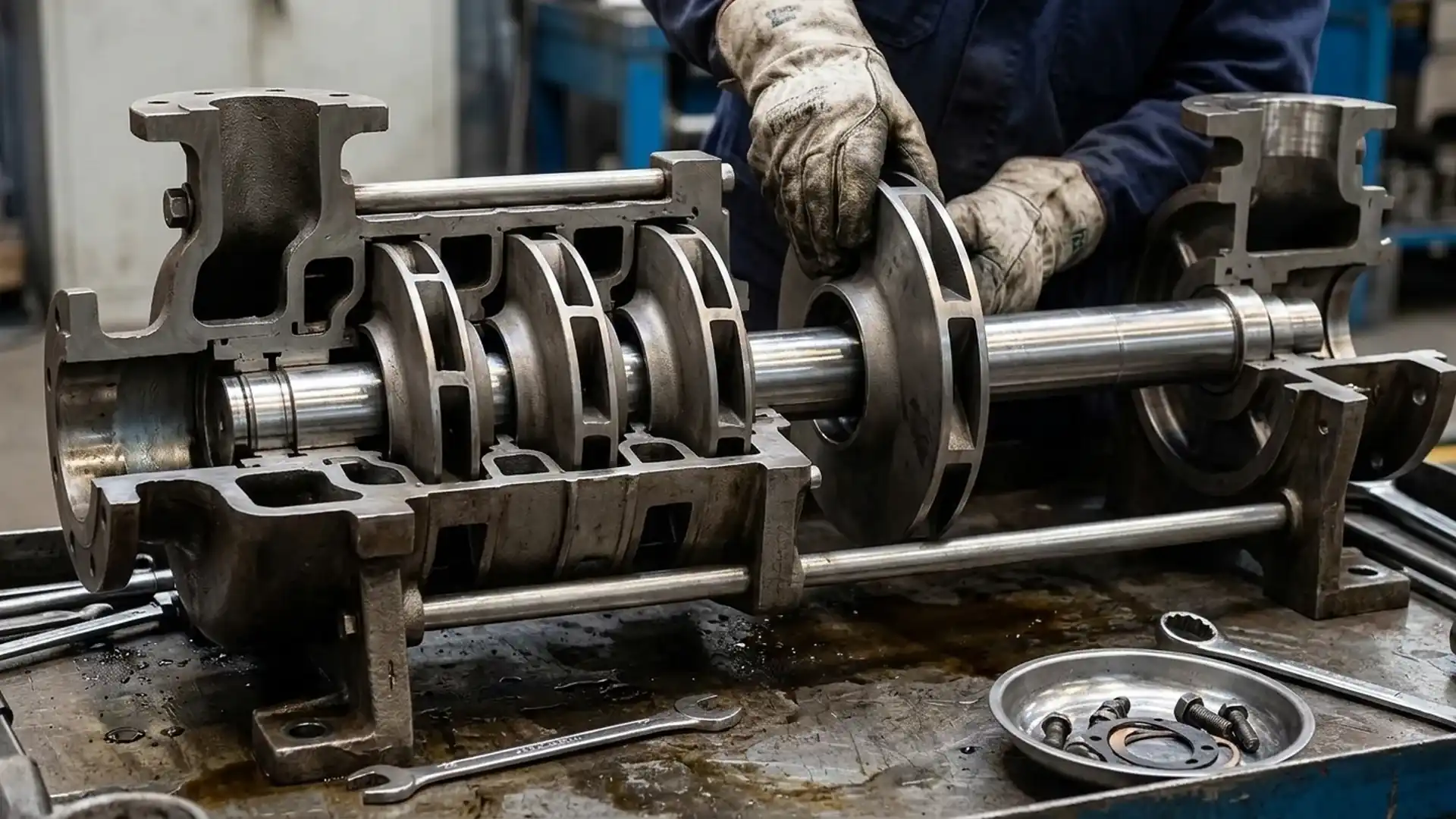
Each impeller in a multistage pump does the same basic work: it spins, accelerates the fluid outward, and passes it into a stationary diffuser where velocity energy converts to static pressure. The critical difference from a single‑stage pump is that the fluid leaving the first impeller becomes the supply for the second impeller. The pressure keeps building.
The head added per stage depends on the impeller diameter and rotational speed. In a typical 4‑stage horizontal unit, if each impeller generates 50 meters of head, the pump total is around 200 meters (minus short‑path friction losses). If the application needs 800 meters, you’d be looking at roughly 16 stages. That’s why stage count is not a marketing number—it’s a direct result of the system‑head requirement and the chosen impeller design.
Here’s something buyers often overlook: more stages mean a longer shaft, and longer shafts deflect. That’s a problem you really don’t want near the seal faces. A well‑engineered pump uses intermediate bearing supports or a carefully stiff shaft design to keep deflection in check.
Impellers, Diffusers, and Internal Flow Path
Inside every stage, an impeller rotates inside a diffuser casing (or a volute stage in some designs). The diffuser channels direct flow into the next impeller’s eye, ideally with minimal turbulence. Clean diffuser vane geometries and smooth interstage passages make a measurable difference in efficiency and vibration.
If you open a competitive bid and see two pumps both rated 300 m³/h at 600 m head, but one has 10 stages and the other 12, something is different: impeller diameter, rotational speed, or hydraulic design efficiency. More stages don’t automatically mean “better”—they can mean a cheaper, smaller‑diameter impeller that needs extra stages to reach the head. Ask for the specific speed per stage and compare the efficiency at BEP, not just stage count. That’s where the real energy‑cost difference hides.
Why Multistage Pumps Reach Higher Head Than Single-Stage Pumps
A single‑stage centrifugal pump can increase head by enlarging the impeller diameter or spinning faster. But diameter is limited by casing size and casting cost, and speed is limited by NPSH, material strength, and mechanical loads. Practically, beyond 15–20 bar (≈150–200 m head for water), single‑stage designs become inefficient and vibration‑prone.
A multistage pump avoids those limits by stacking smaller impellers optimized for higher-head duty. Depending on the hydraulic design, impeller sizing, and operating point relative to BEP, many industrial multistage pumps maintain comparatively strong efficiency in high‑head service because each stage operates within a moderate specific-speed range. In some high‑head applications, a single‑stage alternative pushed beyond its practical impeller diameter or speed range may operate at noticeably lower efficiency or require a much larger, heavier motor, although actual performance remains highly project‑ and design‑dependent.
For the buyer, this comparison matters most when you’re considering lifecycle electricity cost. A seemingly small efficiency gap—even two or three percentage points on a typical 250 kW boiler feed pump—can translate into substantial annual savings. In many cases, that saving alone justifies the higher initial cost of a properly selected multistage pump. If you’re comparing configurations, use our detailed breakdown at Single Stage vs Multistage Pump: Which One Should You Choose for Pressure, Flow, and Energy Cost? for a side‑by‑side economic analysis.
| Feature | Single‑Stage Centrifugal Pump | Horizontal Multistage Pump |
|---|---|---|
| Head range (water) | Typically ≤150–200 m | 100 m to 2000+ m (depending on stages) |
| Flow range | Up to several thousand m³/h | Typically up to ~500 m³/h for standard industrial models |
| Efficiency at high head | Drops significantly above 150 m | Design-dependent; many industrial models achieve 70–80%+ near BEP under controlled test conditions. Confirm via certified curve. |
| Maintenance complexity | Simpler; one impeller, fewer wear parts | More complex; multiple impellers, diffusers, balance device |
| Footprint | Compact | Longer footprint; horizontal layout requires space |
| NPSH requirement | Lower due to single suction | First‑stage impeller can be designed for low NPSHr; overall NPSHr still manageable |
| Best for | Low‑to‑medium head, high flow, or when simplicity is key | High‑head, clean‑liquid tasks where energy cost and pressure stability matter |
Horizontal Multistage Pump Design Types and Mechanical Structure
The external casing looks simple; it’s what’s inside that determines reliability.
Ring‑Section vs Barrel‑Type Construction
Ring‑section pumps (also called segmental) are built from a stack of circular diffuser casings clamped together by tie‑bolts. They’re the most common type in mid‑range pressures, because they’re easier to machine, lighter, and generally more cost‑effective. The drawback: pressure containment depends on those tie‑bolts, and a gasket leak between stages can be hard to fix without a full strip‑down.
Barrel‑type (sometimes called double‑case) pumps enclose the entire stage assembly inside a thick outer casing—imagine a removable inner cartridge sliding into a pressure vessel. This design is standard in high‑temperature, high‑pressure boiler feed service, especially above 100 bar, where thermal expansion and safety demand rigid containment. They’re heavier, more expensive, but far more forgiving under thermal cycling because the inner assembly can be pulled without disturbing the suction and discharge piping.
If your application is 25 bar cold water, you don’t need a barrel. If it’s 120 bar, 160°C boiler feed water, you almost certainly do. The supplier should be able to explain why one design is being proposed over the other.
| Design type | Pressure capability | Maintenance access | Relative cost | Common industries |
|---|---|---|---|---|
| Ring‑section (segment) | Typically up to ~60–80 bar in standard industrial designs | Disassembly requires unstacking stages; OK in clean, accessible installations | Lower | Industrial water boosting, RO feed, fire systems |
| Barrel (double case) | Often used above 100 bar in specialized boiler‑feed and power‑generation designs; exact limits depend on manufacturer design standards and project conditions | Inner cartridge pulls out without disturbing suction/discharge piping | Higher (heavier, more metal) | Power plant boiler feed, high‑pressure industrial processes |
Back‑Pullout Maintenance Design
Many horizontal multistage pumps use a back‑pullout arrangement: the bearing housing, shaft, and complete rotor assembly can be pulled backward out of the casing without removing the suction and discharge flanges from the piping. This design can significantly reduce maintenance time in many installations compared with pumps that require piping disconnection for rotor access.
When you’re comparing quotes, ask the supplier: “Is this a back‑pullout design?” If yes, ask to see the sectional drawing that shows the split line and how the rotor is withdrawn. If the answer is no, you need to accept that any impeller or seal repair will add significant labor cost over the pump’s life. Not a deal‑breaker, but a life‑cycle‑cost factor that belongs in your TCO calculation.
Axial Thrust Balancing Methods
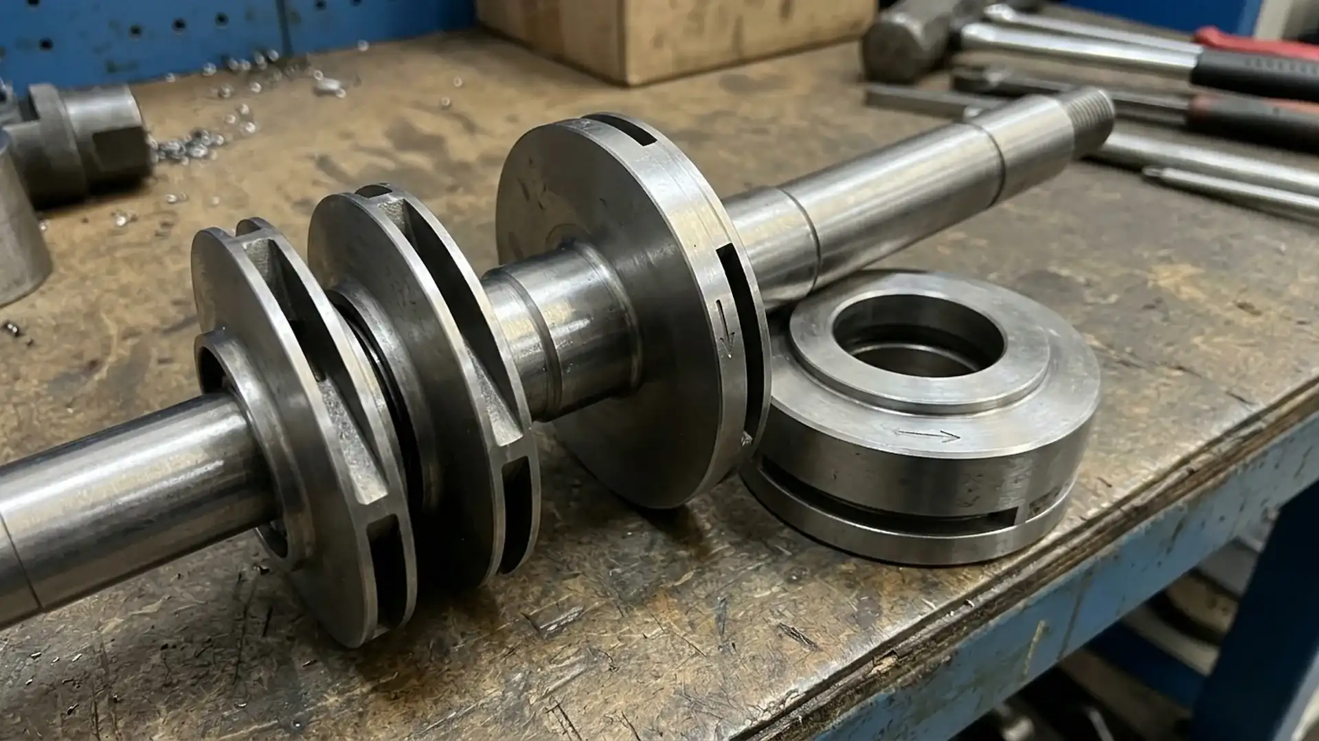
Multistage pumps generate huge axial thrust—the force pushing the shaft along its axis toward the suction end. Each impeller creates a pressure difference that adds to the total thrust. Left uncontrolled, it overloads thrust bearings, wrecks mechanical seals, and causes rapid wear.
Three common strategies: - Balancing disc: A rotating disc mounted behind the last‑stage impeller, with a variable clearance that automatically adjusts thrust based on pressure. It’s self‑compensating but sensitive to wear; as the disc face wears, internal leakage increases, reducing volumetric efficiency. - Balancing drum: A fixed‑clearance drum that counterbalances thrust without variable leakage. More stable over time, but requires precise manufacturing and may not adjust to sudden load changes as smoothly as a disc. - Opposed impellers: Some designs split the impeller groups to face opposite directions, cancelling thrust mechanically. Effective but increases pump length and complexity.
For the buyer, the real question is: “What balancing mechanism is used, and what is the expected internal leakage rate at rated flow?” A well‑designed balancing system should keep thrust loads within the bearing’s published limits. Request supplier confirmation that the design thrust loads remain within bearing limits and that the balancing method is suited to the intended operating range, especially if the pump will run across variable speeds or fluctuating flow conditions.
Pressure Capability, Efficiency, and Operating Limits
Typical Head and Pressure Ranges
A small industrial horizontal multistage pump with four to six stages can deliver roughly 200–400 m head (≈20–40 bar). Mid‑range units with 10–14 stages may reach 600–1000 m, depending on impeller geometry and speed. Ring-section pumps are commonly used up to approximately 60–80 bar in standard industrial service, while specialized barrel-type pumps for boiler‑feed or power‑generation projects can be engineered for substantially higher pressures and heads based on manufacturer design limits, applicable standards, and operating temperature. The key variable is always the number of stages times the head per stage, minus losses.
But head ratings are useless without the corresponding flow. A pump that makes 800 m head at 20 m³/h may only reach 600 m at 40 m³/h. The only way to confirm is to have the supplier’s certified performance curve in your hand, with BEP clearly marked and the allowable operating range defined (typically 70–120% of BEP flow, but that varies). If the curve looks suspiciously flat or shows an unrealistic peak efficiency, ask for the test‑stand data.
Efficiency Curve and Best Efficiency Point

A multistage pump’s efficiency curve can be steeper on the high‑flow side than a single‑stage pump’s, depending on specific speed and hydraulic design, meaning efficiency drops faster when you push flow beyond BEP. Operating even 20% above BEP can increase power demand noticeably and raise the local fluid velocity to levels that accelerate erosion in diffuser vanes.
The BEP is where pump vibration is lowest and bearing life is longest. For continuous‑duty applications (like boiler feed), you want the operating point close to BEP—preferably within 5–10% of it—and ideally slightly to the left (lower flow) rather than to the right, because over‑flowing can cause suction‑specific speed problems and NPSH‑related cavitation.
When you receive a quotation, plot your system curve on the same graph. If the intersection falls outside the pump’s preferred operating region (which the supplier should clearly state), walk away—it will never run right.
NPSH and Cavitation Risk
The Net Positive Suction Head required (NPSHr) by the first‑stage impeller is typically low in well‑designed multistage pumps—often 2–4 meters—because the first impeller can be sized specifically for suction conditions. However, if your installation has a marginal NPSHa (available), the first stage will cavitate just like any other pump. The damage isn’t always immediately audible; it starts as erosion at the impeller eye vane tips, gradually eating away metal and increasing vibration.
Cavitation damage in a multistage pump is especially expensive because the impeller replacement often requires disassembling multiple stages. That’s a full‑day teardown, not a quick cartridge swap. Compare NPSHa (calculated on site) against NPSHr plus an application‑appropriate safety margin. In stable cold‑water service, at least 1 meter may be adequate, while 1.5–2 meters or more should be considered for variable‑speed, hot‑water, or other critical‑duty applications.
VFD Compatibility and Part‑Load Operation
Horizontal multistage pumps generally work well with variable‑frequency drives, but there are two traps: - At low speed, the balancing disc or drum may not generate enough counter‑force, momentarily overloading the thrust bearing. Confirm that the balancing design is effective across the intended speed range. - Operating continuously below 50% of BEP flow can force the impellers into high‑pressure unsteady flow recirculation zones, which can cause low‑frequency pressure pulsations and damage. If your system requires prolonged low‑flow operation, a bypass line or a smaller duty‑standby pump pair is usually a better solution than relying on VFD alone.
For more detail on matching system pressure to pump capability, the selection logic in How to Select a Multistage Pump for High-Pressure Water Systems covers pressure calculation and efficiency trade‑offs step by step.
Common Industrial Applications for Horizontal Multistage Pumps
Boiler Feed Water Systems
This is the classic high‑stakes application. A horizontal multistage pump pushes feedwater into a boiler at pressures that oppose the steam drum pressure—often 60–150 bar. The pump must handle water temperatures from 80°C up to 160°C or more, which means careful material selection (carbon steel or alloy casing, stainless internals), mechanical seals rated for boiling point, and a barrel‑type design if pressure and temperature climb.
Boiler feed pumps run almost continuously. Even a 1‑point efficiency difference can translate into thousands of dollars in electricity over a year. And because boiler trips are expensive, the pump must have extremely low vibration and stable performance at part load during startup. For critical boiler‑feed service, consider specifying a witnessed factory performance test at rated temperature rather than relying only on cold‑water hydraulic tests, noting that hot‑condition testing may require separate contractual agreement and added cost.
Reverse Osmosis and High‑Pressure Water Supply
RO membranes need consistent high pressure (15–70 bar) to overcome osmotic pressure. Horizontal multistage pumps fit perfectly because they deliver steady pressure with minimal pulsation, and their flat efficiency curve around BEP allows a small flow turndown without energy waste.
For large RO trains, you’ll often see a high‑pressure multistage feed pump with a separate booster pump upstream. The booster provides the required NPSH to the high‑pressure pump. Ask the supplier if they recommend an integrated booster on a common skid—that simplifies installation but may complicate maintenance access.
High‑Rise Building Pressure Boosting
In tall commercial or residential towers, pressure‑boosting stations use multistage pumps to lift water from basement tanks to upper‑floor zones. Horizontal designs are common in mechanical rooms where space isn’t as tight. They’re easier for maintenance staff to work on than vertical inline pumps, and the back‑pullout feature is valuable when you’ve got 40 floors of tenants expecting water.
One application‑specific check: in booster systems, the pump may run on a pressure transmitter that starts and stops frequently. Make sure the pump’s bearing and seal are rated for the expected number of starts per hour—exceeding that rating shortens seal life dramatically.
Fire Protection and Industrial Utility Systems
Multistage pumps serve in jockey‑pump and main‑fire‑pump configurations where high pressure is needed from a limited supply line. They’re also used in high‑pressure washdown, hydrostatic test rigs, and industrial wash systems. In every case, the liquid must be clean and free of suspended particles; debris can score the diffuser vanes and wear rings quickly.
When a project specification calls for a high pressure water pump for fire service, the pump must often meet NFPA 20 or local equivalent. That adds requirements for driver type, controller listing, and suction arrangement. A horizontal multistage pump that meets the hydraulic spec may still not meet the fire‑listing requirements—confirm with the supplier early to avoid a costly design revision.
For a broader look at where multistage pumps fit versus other types in high‑head duty, see Multistage Pump Selection for High-Head Water Supply: When to Use It and What Data Suppliers Need.
| Application | Typical head range | Temperature range | Key pump requirements |
|---|---|---|---|
| Boiler feed | 60–150+ bar | 80–160°C+ | Barrel design, high‑temp seals, material compatibility, witnessed test |
| RO high‑pressure feed | 15–70 bar | 5–45°C | Steady pressure, efficiency at continuous duty, corrosion‑resistant internals |
| High‑rise pressure boosting | 10–40 bar | 5–30°C | Back‑pullout access, multiple start/stop rated, moderate noise |
| Fire protection (booster/jockey) | 8–30 bar | Ambient | Certified performance curve, compliance with fire standards, listed motor/controller if required |
| Industrial wash/test rigs | 20–100 bar | Ambient to 60°C | Clean‑liquid only, durable mechanical seals, abrasive‑resistant wear rings if water has minor particles |
Material Selection, Seals, and Durability Considerations
Cast Iron vs Stainless Steel vs Alloy Materials
The wetted parts of a horizontal multistage pump—casing, impellers, diffusers, shaft—must handle the fluid chemistry and temperature without corrosion, erosion, or galvanic problems. For standard industrial cold water, ductile cast iron casings with bronze or stainless impellers work well and keep cost down. When water has elevated chloride levels (coastal locations, certain process waters), 304 or 316 stainless steel is often required to avoid pitting corrosion in stagnant areas.
At high temperatures, carbon steel or low‑alloy steel casings with 12–13% chrome stainless internals are common in boiler feed pumps. The thermal expansion rates must match, or interstage gaskets shift and leak. Don’t assume upgrading to all‑stainless is always better—it can create galling problems at tight‑clearance wear rings, especially in hot water. Ask the supplier to show a material‑compatibility table for your specific water analysis.
Mechanical Seal Selection
Most horizontal multistage pumps use cartridge mechanical seals for the shaft penetration, and the seal environment is tough: high pressure, sometimes hot water, and constant thrust‑induced shaft movement. A single cartridge seal with a hard‑on‑hard face combination (e.g., silicon carbide vs silicon carbide) and elastomers compatible with the fluid temperature is the baseline.
For boiler feed or hot water above 120°C, a cooled seal support arrangement such as a Plan 23 configuration is a common industrial approach, although the exact seal plan depends on temperature, pressure, fluid properties, and the OEM or seal supplier’s design practice. If the supplier hasn’t mentioned seal cooling, ask how the seal chamber temperature is controlled. An uncooled seal in hot water can vaporize the fluid film and fail prematurely. If the pump handles a fluid that crystallizes or polymerizes on contact with air, dual pressurized seals with a barrier fluid are often considered, but the final arrangement should be confirmed with the seal supplier and pump OEM.
Don’t accept “standard mechanical seal” on a data sheet without the material grades and flush plan number. A seal that works at 30°C cold water can fail in hours at 140°C.
Temperature and Corrosion Considerations
When temperature goes up, material strength goes down, and thermal expansion opens clearances. That means the pump’s performance at 120°C may not match the cold‑water test curve. Buyers should request a correction factor for hot‑water performance, or better, a performance test at operating temperature.
Corrosion often attacks at the tightest clearances: wear rings, balancing device faces, and seal faces. Even minor pitting here changes internal leakage and reduces efficiency. If your water is aggressive (high chloride, low pH, dissolved oxygen), specify upgraded materials for these close‑clearance parts even if the main casing stays cast iron. It’s a small incremental cost that significantly extends service life.
| Fluid condition | Recommended casing material | Wetted internal parts | Seal considerations |
|---|---|---|---|
| Clean cold water, pH 6–8, low chloride | Ductile iron or cast iron | Bronze or 304 SS impellers, 420 SS shaft | Single cartridge, SiC‑SiC faces |
| Softened/filtered water, mild corrosive | 304 SS | 304/316 SS | Same, but check elastomer |
| High chloride water (>250 mg/L) | 316L SS or duplex SS | 316L or duplex | Single or dual seal depending on temperature |
| Hot water (80–140°C) | Carbon steel or alloy steel casing | 12–13% Cr stainless | Plan 23 cooled seal, high‑temp gaskets |
| Boiler feed (140°C+) | Forged or cast alloy steel barrel | Chrome stainless internals, hardened wear rings | Dual pressurized or cooled seal |
What Buyers Should Verify Before Ordering a Horizontal Multistage Pump
Required Technical Data for RFQ
A vague inquiry—“need high‑pressure pump for 30 bar”—gets you a standard‑range pump that might fit the pressure but not the real service. A proper RFQ for a horizontal multistage pump should include at minimum:
| Field | Your input / options |
|---|---|
| Required flow rate (m³/h or GPM) | |
| Total dynamic head (m or ft) | |
| NPSH available at pump suction (m) | |
| Fluid type and chemistry (chloride, pH, hardness, solids) | |
| Fluid temperature range (°C) | |
| Continuous or intermittent duty? | |
| Required motor efficiency class (IE3, IE4, etc.) | |
| Power supply: voltage, phase, frequency | |
| Required design type (ring‑section / barrel) | Leave blank if unsure; ask supplier to recommend with justification |
| Flange standard (ANSI, DIN, JIS) | |
| Required test standard (ISO 9906 Grade 1 or 2) | |
| Preferred seal flush plan if known | |
| Spare parts to quote with pump |
Submitting that table, even partially filled, signals a technically competent buyer. It also forces the supplier to propose a specific pump model and provide a technical data sheet, not a generic flyer.
Performance Testing and QC Documentation
As a buyer, you should require a hydraulic performance test report for every pump you order. Specify the test standard and acceptance grade in your RFQ or contract specification—many projects reference ISO 9906 grades, but the required edition, tolerance class, and test scope depend on customer standards, application criticality, and manufacturer capability. Critical services such as boiler feed or large RO trains may justify tighter tolerances than general utility service, so make your requirement explicit. The test curve—head, efficiency, power, NPSHr—must be plotted against flow. Ask for the test data points, not just the smoothed curve, and compare the efficiency at BEP with the published curve.
Additional documents that separate professional suppliers from trading companies: - Material test certificates (3.1 or 3.2 per EN 10204) - Hydrostatic pressure test record for the casing - Impeller dynamic balance report - Shaft runout measurement record - Assembly inspection checklist with inspector sign‑off - Motor nameplate photo and test certificate
For critical applications (boiler feed, large RO trains), request an inspection hold point and a witnessed test. The extra cost is negligible compared to the risk of receiving a pump that underperforms at site.
Spare Parts, Lead Time, and Serviceability
A horizontal multistage pump has many wear parts: impeller wear rings, inter‑stage bushings, balancing disc or drum faces, shaft sleeve at the seal, and the mechanical seal cartridge itself. Ask the supplier to include a recommended spare parts list for initial operation—typically the first year or two—with delivery lead times clearly stated. Standard impellers may be in stock, but a custom‑trimmed impeller for your specific performance point could take weeks.
Export packaging matters, especially for multistage pumps where the shaft is long and heavy. The pump should be bolted to a steel‑channel skid or a wooden crated base that supports the motor and coupling rigidly. Shaft locking during transport prevents rotor motion that could damage seal faces or bearings in transit. Confirm that the packaging specification is documented in the quotation—not just “standard export packing.”
If you’re purchasing as a distributor or OEM, ask about partial‑disassembly options for container optimization. A fully assembled long pump may require an open‑top container or break‑bulk shipment, raising freight cost. Some suppliers offer to ship the pump with the rotor removed and packed separately, but that requires qualified reassembly on site.
For direct access to high‑pressure, high‑efficiency multistage pump solutions with factory pricing and OEM support, see High‑Pressure, High‑Efficiency Multistage Pump Solutions.
FAQ — Horizontal Multistage Pump Buying and Engineering Concerns
Here are the five questions engineering buyers most often ask once they’ve read the data sheets but before they feel ready to place an order.
How much head can a horizontal multistage pump generate?
A standard ring‑section horizontal multistage pump can deliver from about 100 meters up to approximately 800 meters head, depending on the number of stages, impeller diameter, and operating speed. Specialized barrel‑type pumps used in boiler‑feed or power‑generation service may be engineered for much higher heads, but those limits are manufacturer‑ and project‑specific rather than universal catalog values. The actual head for your pump will be shown on the certified performance curve at the specified flow; total head per stage is usually between 30 and 65 meters for typical 2‑pole (3000/3600 rpm) designs. When comparing quotes, don’t just ask “how many meters?”—ask “what is the head at our design flow and at BEP?”
When is a horizontal multistage pump better than a single-stage pump?
It’s better when the system’s total dynamic head exceeds approximately 150–200 meters for water, or when a single‑stage pump would need an impeller so large or a speed so high that efficiency drops below what a multistage can deliver. Also, if the system benefits from a flatter efficiency curve across a range of flows, a multistage often outperforms a single‑stage. But if head is below 150 m and flow is high, a single‑stage double‑suction pump is usually simpler, cheaper, and easier to maintain.
What causes axial thrust failure in multistage pumps?
The most common cause is wear of the balancing device surfaces. As a balancing disc face wears, internal leakage increases, and the disc moves closer to the stationary counter‑face. Eventually, it can bottom out and lose its ability to automatically adjust thrust. Rapid wear can be accelerated by dirty fluid, cavitation, or operation far from BEP. Bearing overload from thrust failure first shows up as increased vibration at the non‑drive end and rising bearing temperatures. Regular monitoring of vibration and seal leakage trends is the best early warning.
Can horizontal multistage pumps handle hot water?
Yes, but not just any pump. For water above 80°C up to about 140°C, you’ll need a pump with a hot‑water mechanical seal, typically with a cooling flush (Plan 23), and materials that maintain strength at temperature. For boiler feed above 140°C, you’re looking at a barrel‑type design with chrome‑stainless internals and careful thermal expansion management. Confirm the maximum allowable operating temperature from the supplier’s data sheet; exceeding it voids warranty and risks seal failure.
What maintenance points matter most for long‑term reliability?
The four items to watch: mechanical seal leakage (monitor drip rate), bearing temperature and vibration, internal clearances at the balancing device (trend the balance line pressure or leakage rate if possible), and the condition of the first‑stage impeller inlet for cavitation damage. Annual inspections should measure wear ring clearances against new‑part tolerances; if they exceed twice the initial clearance, plan a replacement to prevent efficiency loss and cascade damage. Keep a logbook—a gradual change tells you more than any single reading.
Conclusion
A horizontal multistage pump is a reliable high‑head machine only when it’s matched to the actual system curve, the internal thrust balancing is designed for the intended speed range, and the materials are compatible with your water chemistry and temperature. Shortcuts in any of those areas shift cost from the purchase price to your maintenance budget.
The differences between suppliers are rarely visible on a dimension drawing. They show up in the test curve, the balancing device design documentation, the seal specification, and the spare parts lead time quote. That’s where you should spend your evaluation time. Ask for data, verify the design logic, and request a certified performance curve at your operating point. That single document, backed by a factory test, is still the most honest representation of what you’re actually buying.
Get A Quote

Get A Quote
0 Comments